
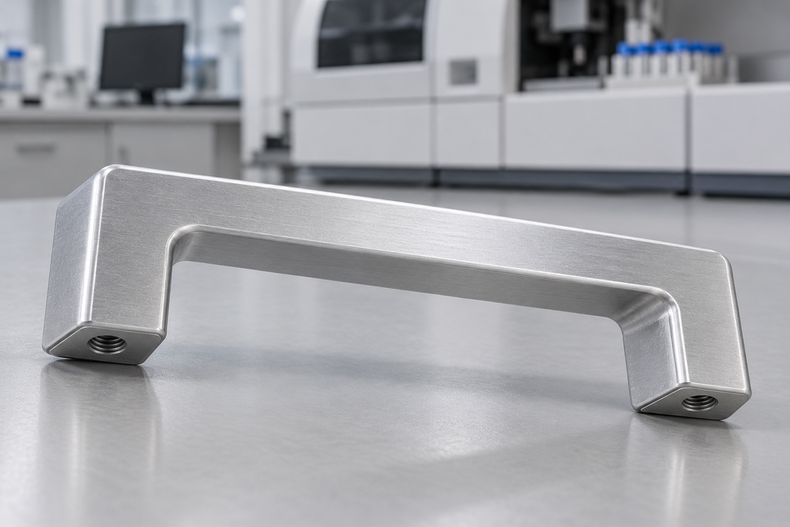
Representative proposed service drawer pull
This representative example describes a proposed one-piece 6061 aluminum bridge pull handle for a medical analyzer service drawer. The illustrative component has a straight rectangular-section grip, two short end legs, coplanar feet and one blind female thread entered from each foot's underside. It is not a patient support or whole-machine lifting point. No actual customer delivery or manufactured sample is described. No achieved tolerance, load capacity, fatigue life, retention result, antimicrobial performance, sterile status, medical certification or validated equipment safety is claimed as an actual measured production outcome.

Review the released service arrangement
The proposed order would begin with a controlled handle drawing and model, actual drawer panel, fasteners, service travel, installation method and inspection scope. The supplier would clarify useful foot contacts and hand access rather than infer a complete mounting arrangement from the bridge shape. Missing dimensions or contradictory requirements would be resolved before cutting material. The machining review would remain separate from the equipment team's load, ergonomic and service-use evaluations for the actual assembly. A similar catalog handle would serve as background only, not authorize material substitution or a transfer of its rating.
Preserve the approved aluminum identity
The material package would define the approved 6061 condition, stock form, required evidence and any final surface treatment. Blanks would remain traceable to their lot through milling, finishing and shipment. The supplier would review stock allowance and holding regions before selecting the route. Silver appearance would not establish equivalence to a cast or bent handle, nor justify another alloy. Material records would identify the component material, not demonstrate antimicrobial behavior, cleaning compatibility, electrical bonding or sterile delivery. Any such requirements would need a separately agreed application-specific scope and evidence.
Establish feet and setup references
Initial operations would establish the approved references used to relate both feet, mounting features and bridge. The sequence would consider roughing, finishing, setup transfer and the component's unclamped state. The supplier would avoid accepting geometry only while the handle was forced into position. Chips would be removed from locating contacts before reorientation. Intermediate checks could support process development, but final acceptance would address the drawing's relationships after relevant machining and purchased surface processes. A raw edge or convenient fixture coordinate would not silently replace a functional mounting reference.
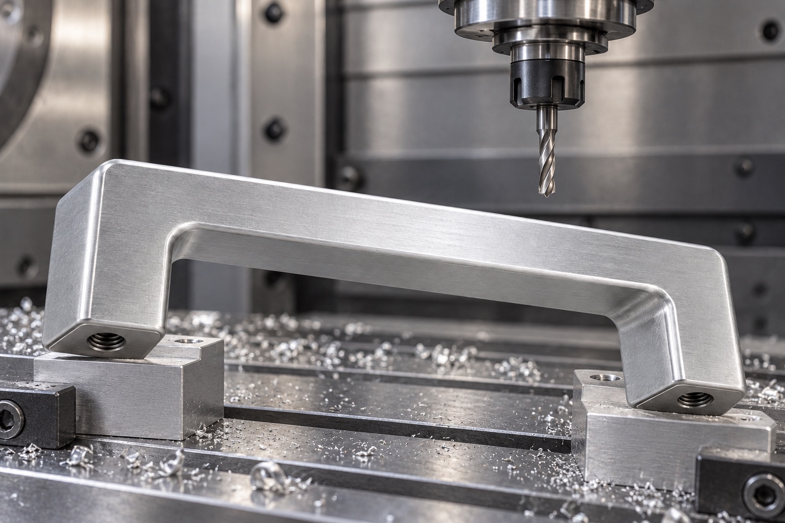
Mill the open bridge and grip
The open region beneath the grip would follow approved clearance, leg geometry, inside radii and useful contact requirements. Tool access and remaining material would be reviewed before production. The supplier would not enlarge the opening, reduce a leg or add an informal grip sleeve merely to improve one hand-fit observation. Authorized changes would enter controlled documents. The bridge would remain a specified equipment component, not evidence of a safe load or suitable ergonomics for every operator, glove and service posture used around an unspecified medical analyzer enclosure and drawer configuration.
Produce the underside mounting threads
Each blind thread would follow the released designation, hand, useful engagement, entry, depth and position relative to its foot. Drilled depth would not be reported as usable thread length. Tool clearance and remaining material would be reviewed before manufacture. The supplier would not change screw size or break through the grip to accommodate an unidentified fastener. Any approved adjustment would remain traceable. A gauge result would address its specified characteristics, not establish sufficient engagement, resistance to loosening or load capacity of the complete handle, panel and screw arrangement.
Finish without changing the mounting seats
Finishing would examine grip boundaries, internal corners, foot faces and thread entries for attached material or unwanted sharp features. Released edge requirements would preserve useful mounting contacts and the defined hand-clearance envelope. Cleaning and final treatment would follow the purchased scope with relevant finished-state checks. A smooth feel would not establish measured particle behavior, antimicrobial action, sterile delivery or validated cleaning. Uncontrolled polishing would not hide damage or change foot seating to make an unidentified panel fit before the agreed dimensional report and any optional assembly observations were completed.
Inspect the related mounting features
The inspection plan would identify methods for both feet, their relationship and spacing, thread position, bridge geometry and required clearance dimensions. Support, final treatment and measurement contact would be specified. Outside-size measurements and a thread-entry check alone would not verify every controlled characteristic. Inaccessible or ambiguous requirements would be clarified before production. Supplier and purchaser would agree the actual finished-component acceptance method rather than substitute a favorable drawer-fit observation. Reports would retain revision and material identity, keeping component dimensions distinct from the installation and operating behavior of the complete medical analyzer.
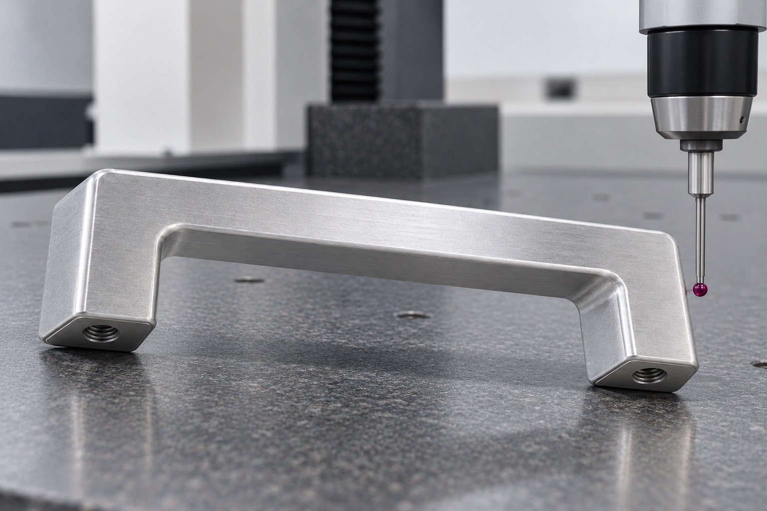
Prepare first-part evidence without values
The proposed first-part package would identify drawing revision, material lot, numbered requirements and agreed inspection methods. No numerical results are supplied because this representative example has no manufactured sample or measurement record. Actual nonconformance and authorized changes would remain traceable. Accepted dimensions would not demonstrate load capacity, fatigue, screw retention or ergonomic suitability. A photograph of a probe would illustrate a possible inspection setup, not prove that a particular tolerance had been achieved. The record would separate measured component characteristics from optional assembly observations and independent complete-equipment evaluation.
Limit any optional service-use demonstration
An agreed trial could examine foot seating, screw access, hand space and specified drawer movement with identified panel, fastener and handle revisions. The installation method and approved washers or inserts would be recorded. Unexpected rocking or interference would be reviewed before changing the component or panel. Successful hand operation would not qualify load, fatigue, misuse resistance or medical equipment safety. Trial handles would remain distinguishable from accepted production. Approved modifications would become revised documents rather than make a hand-adjusted specimen an informal gauge for other drawers or service arrangements.
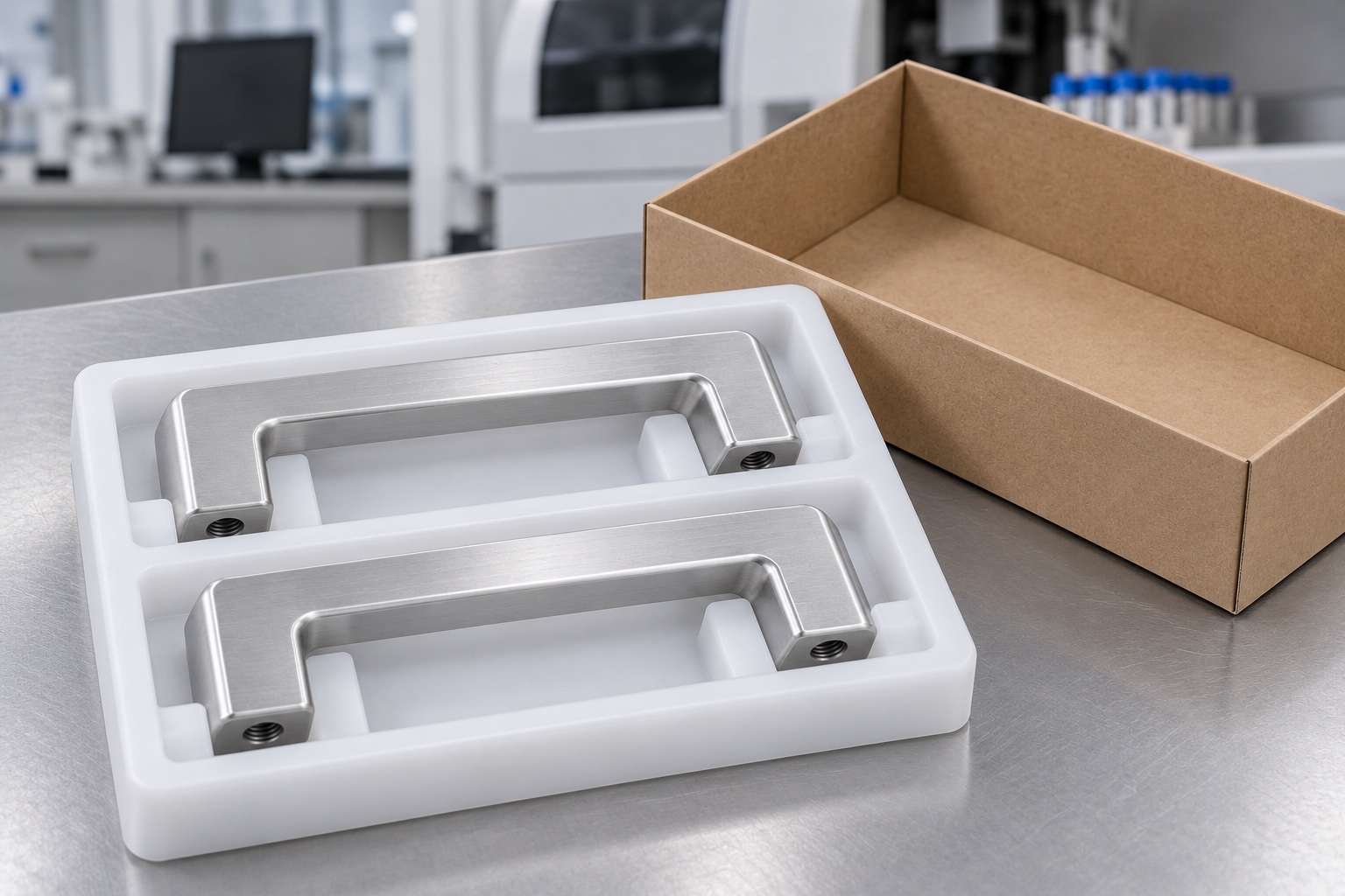
Protect bridge, feet and thread entries
Finished handles would be separated so adjacent components and loose hardware could not strike the grip, mounting seats or threads. Packing support would avoid bending the bridge or squeezing the legs. Protective packaging would not imply sterile delivery. Lot, revision, treatment and inspection status would accompany the shipment. Receiving checks would distinguish height, spacing and thread variants, prototypes and released production. These controls would preserve the accepted component and its identity before the equipment team performed approved installation and its independent service-use, maintenance, cleaning or other application evaluations.
Keep a controlled repeat-order baseline
The final package would retain the released geometry, actual panel and fasteners, foot and clearance requirements, material evidence, final process, inspection report and protective packing scope. Approved prototype changes would enter revised documents before repeat manufacture. Changes in panel, screw length, grip treatment or service conditions would trigger review rather than rely on previous observations. This representative workflow illustrates a traceable CNC project without inventing customer history or performance results, and without confusing a conforming aluminum drawer pull with a qualified patient-support, restraint or whole-machine lifting component for medical use.
Manufacturer background reference: www.ganternorm.com.
FAQ
Is this an actual customer delivery?
No. It is a representative proposed CNC manufacturing workflow with illustrative images. There is no named customer, manufactured sample, measurement record or achieved performance result. A real project would require its own released documents, production records and measured acceptance evidence.
Does this example give the handle a load rating?
No. No load or fatigue result is available. The actual handle, panel, screws, installation and intended service conditions would need separate evaluation. Component conformity and a favorable hand operation do not establish a safe rating or medical equipment safety.
Why are the mounting threads specified as blind?
Their intended direction, useful length and remaining material are part of the released design. They should not be replaced by through holes or different threads for convenience. The approved assembly would define fasteners and required engagement instead of relying on an unidentified screw.
Would a flat panel replace dimensional inspection?
Not automatically. An identified panel can support a limited seating observation. The feet, spacing, thread position and other specified relationships still need agreed inspection methods in the defined final state. Forcing a rocking handle flat would not resolve the dimensional requirement.
Are antimicrobial or sterile results included?
No. Smooth aluminum and protective packaging do not establish antimicrobial action, validated cleaning or sterile delivery. Any such property would need a separately purchased and verified scope for the actual finished component and intended medical equipment environment.
What would be retained for later orders?
Retain released model and drawing, panel and fasteners, foot geometry, thread engagement, hand clearance, material, final treatment, inspection and packing requirements. Approved changes must enter controlled revisions instead of relying on a modified prototype or informal service-use memory.

tanghangyun@oemach.com