
A robot mounting bracket may look simple, but its function depends on the relationship between the base plane, the two upright ears and the fastening holes. Any shift between these features can appear only after the mating shaft or module is installed.
For this 6061-T6 bracket, OEMach treated the base as the primary installation datum and the ear holes as the connection interface. The process plan then controlled ear deflection, countersunk-hole seating, side features, natural-anodized appearance and transport protection.
Project Snapshot
| Item | Project detail |
|---|---|
| Application | Robot joint or actuator mounting and locating bracket |
| Material and finish | 6061-T6 aluminum with natural anodizing |
| Key features | Long base, two upright ears, ear holes, countersunk mounting holes, side hole and relief opening |
| Control focus | Base flatness, ear parallelism, hole position, countersink depth, chamfers, scratches and packaging |
Define The Base As The Installation Datum
The base carries the bracket against the customer structure, while the ear holes locate a shaft, pin or connected module. Countersunk holes must seat the fasteners without lifting or tilting the base.
OEMach identifies the primary base, lateral datum and ear-hole axis before programming. This keeps the process focused on the relationships that matter after tightening rather than on the outline alone.
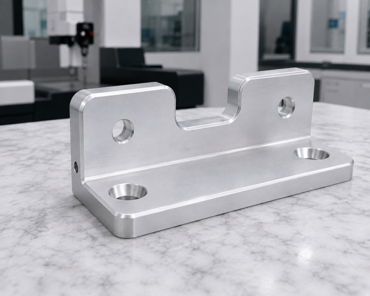
The base plane, two raised ears, ear holes, countersunk mounting holes and relief opening form one installation relationship.
The Upright Ears Can Move During Machining
The ears are relatively tall and thin compared with the base. Uneven cutting force or heavy clamping can cause small deflection, chatter or a change in the free-state spacing. Two holes can pass individual size checks while still being misaligned with each other or with the base.
Controlled support, lighter finishing cuts and a planned cutting sequence reduce this risk. Chamfer size is also kept consistent so the natural-anodized edges remain clean without reducing effective bearing contact.
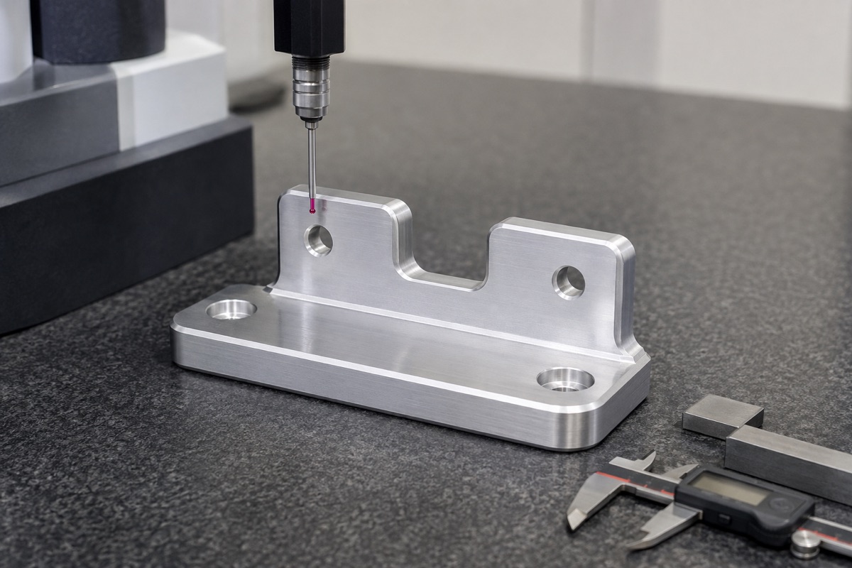
The ear spacing, parallel condition, hole position and base reference are checked in the free state rather than only while the part is clamped.
Stabilize The Base Before Finishing The Ears
The route first establishes the base and side reference, then roughs the outside profile and relief opening while leaving allowance on the ears and critical holes. After stress redistribution, the ear holes, countersinks and side features are finished from the controlled datum system.
Countersink depth and concentricity are verified because they influence screw seating. Side holes require an additional orientation, so datum transfer is planned rather than improvised at the machine.
Natural Anodizing Makes Preparation Visible
Natural anodizing does not hide scratches, material texture or inconsistent tool marks as strongly as a dark finish. The base, outside ear faces and countersink edges therefore receive a pre-finish visual review after deburring and cleaning.
Post-finish inspection checks color consistency, trapped residue, hole condition and any dimensional feature affected by coating. Functional holes can require allowance or masking when the fit is close.
Lead Time And Packaging Follow The Deformation Risk
A typical reference plan is approximately 6 to 9 working days for prototypes and 9 to 14 working days for small batches. Ear-relationship reports, full inspection or appearance samples add work and should be included in the confirmed schedule.
Profile foam supports the base and leaves clearance around the ears. Individual separation prevents surface rubbing and avoids bending loads, allowing the part to enter the customer's assembly trial directly after incoming inspection.
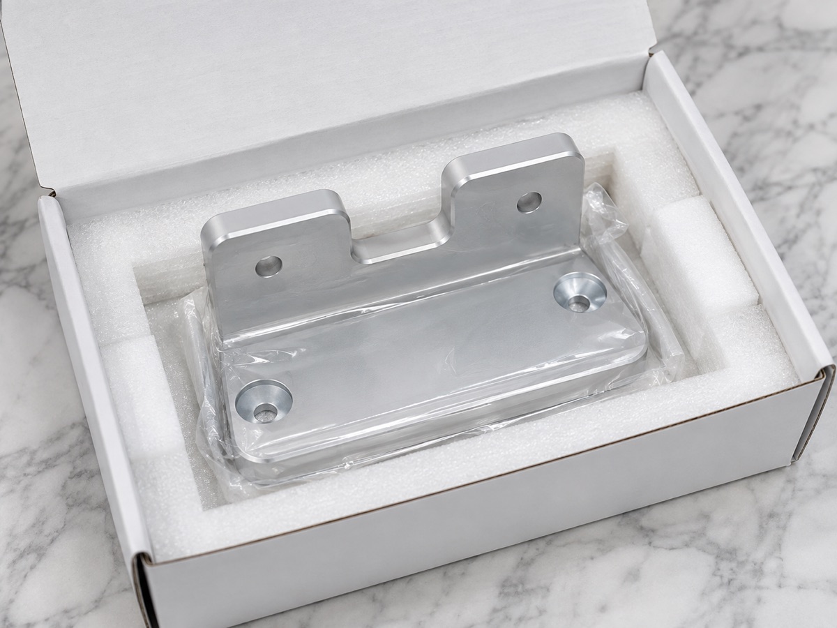
Foam supports the base and leaves clearance around the ears so the natural-anodized surfaces and thin upright features are not loaded in transit.
Case Summary
The key to this robot bracket is not its simple outline but the free-state relationship between base, ears, countersinks and side holes. A datum-led machining route, post-anodize inspection and ear-safe packaging turn that geometry into a reliable assembly component.
FAQ
Why measure the ear relationship in the free state?
A fixture can temporarily hold thin ears in position. Free-state inspection shows the condition the customer receives before assembly force is applied.
What should be checked on countersunk mounting holes?
Diameter, depth, angle, concentricity, edge condition and the resulting fastener seating relative to the base surface should be reviewed.
Does natural anodizing hide machining marks?
No. It often leaves material texture and surface preparation visible, so scratches, tool marks and deburring quality should be controlled before treatment.
How are the upright ears protected in packaging?
The base is supported in profile-cut foam while clearance is left around the ears, preventing compression, impact and part-to-part rubbing.
Ready to get a quote for your CNC machined parts?
Submit your engineering drawings to qiancj@oemach.com. We support prototype sampling and small-batch production with strict tolerance control.