
A robot end flange is more than a thick aluminum disc. Its central step establishes location, the mounting face transfers clamp load, and the hole circles determine whether the end module can be installed without angular or positional error.
For this 6061 aluminum project, OEMach linked machining, inspection, black anodizing and packaging to the same assembly logic. The center bore, locating step, face and two hole circles were treated as one functional feature group rather than separate dimensions.
Project Snapshot
| Item | Project detail |
|---|---|
| Application | Robot end-effector or joint-end connection flange |
| Material and finish | 6061 aluminum, 180-grit bead blast and black anodizing |
| Key features | Thick disc, center bore, locating step, mounting face, inner threaded circle and outer bolt circle |
| Control focus | Step size and roundness, face flatness, hole-circle relationship, thread quality, burrs and cosmetic protection |
Treat The Flange As An Assembly Datum
The central step locates the mating component while the face carries the clamped interface. If either feature shifts relative to the hole circles, the mating part may sit at the wrong attitude even when every hole passes an individual size check.
The review therefore identifies the primary face, center axis and angular clocking feature before the machining route is fixed. Nonfunctional outside diameter is kept separate from the features that control assembly.
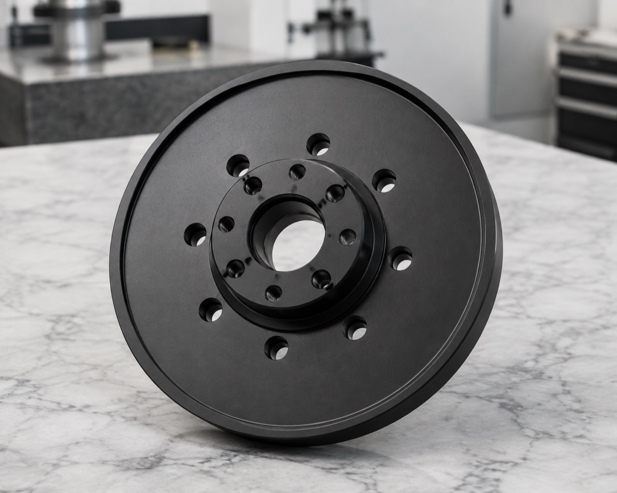
The thick disc combines a central locating step, a through bore and inner and outer hole circles that must share one functional datum system.
The Center Step And Hole Circles Carry The Main Risk
The thick section gives good rigidity, but multiple circles, counterbores and threads still create accumulated positional risk. The inner circle may support location or an auxiliary interface, while the outer circle carries the main fastening pattern.
Hole exit burrs, inconsistent chamfers and tool marks near the step become more visible after black anodizing. A correct part must therefore meet both the positional relationship and the finished appearance requirement.
Machine The Face And Center Before Final Hole Patterns
OEMach first establishes the face and center-axis references, roughs the disc and step with finishing allowance, then finishes the center bore, locating diameter and critical face. The inner and outer hole circles are completed from the same controlled datum chain wherever practical.
Stable drilling and threading tools limit drift across the pattern. Chamfers are kept consistent and deburring is planned before surface treatment so hole mouths remain clean without rounding the locating features.
Inspection Must Follow The Customer's Fastening Logic
First-article inspection covers the center bore, locating step, face flatness, face-to-face parallelism, bolt-circle position, angular relationship, thread gauges, chamfers and cosmetic finish. A locating pin or representative mating feature can be used when functional clocking needs confirmation.
After anodizing, OEMach rechecks visible damage, residue around holes, thread condition and protected locating areas. Masking or coating allowance must be agreed before finishing when the center step has a strict fit.
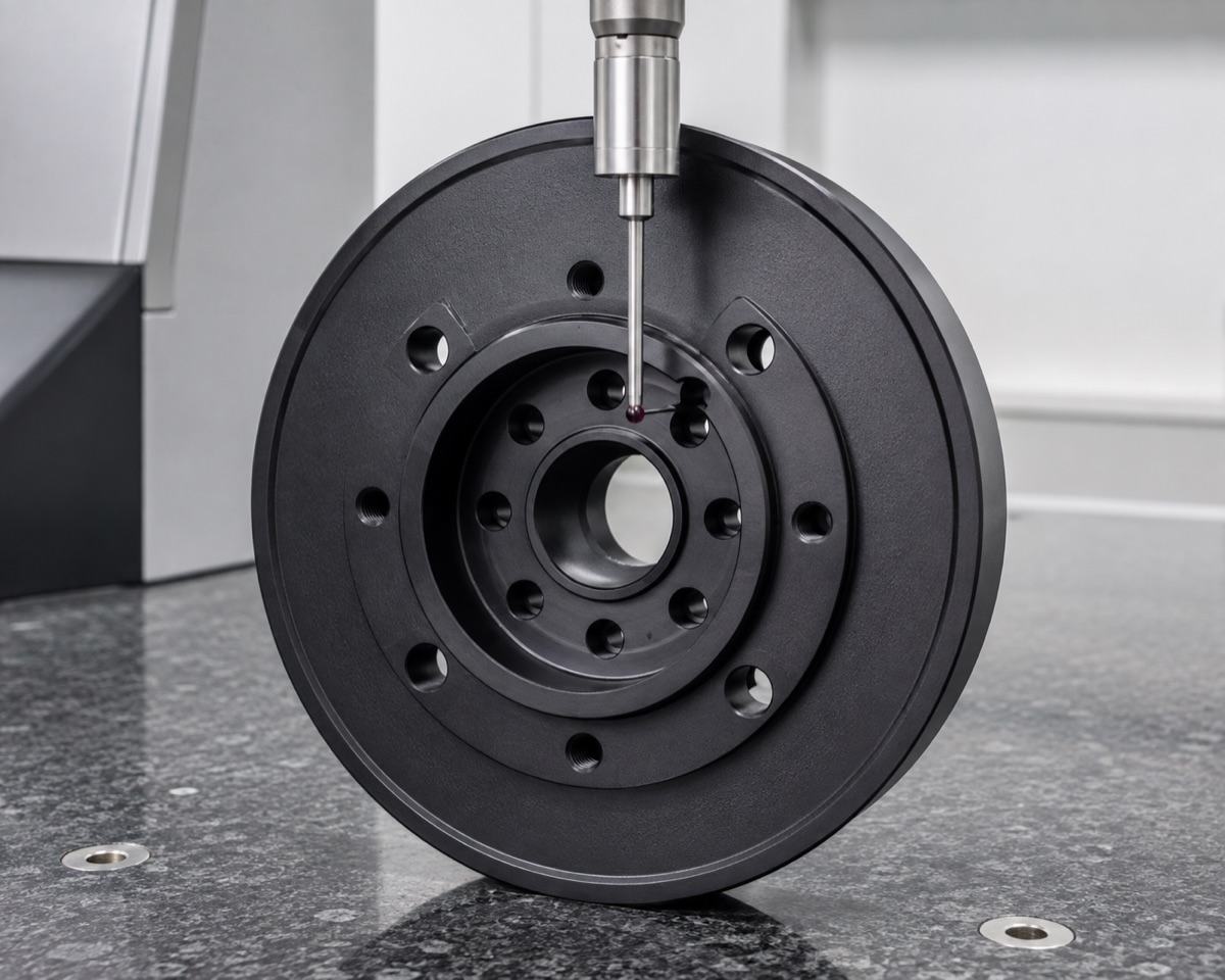
Inspection follows the assembly datum so concentric features, bolt-circle angle and end-face condition are evaluated together.
Lead Time And Packaging Protect The Finished Datum
A typical reference plan is approximately 5 to 8 working days for prototypes and 8 to 12 working days for small batches. Final timing depends on drawing release, inspection scope, anodizing capacity and any full hole-pattern report.
Each flange is supported in foam so the face and central step do not touch hard packaging. A clean protective bag separates the black finish from dust and abrasion, preserving the part through delivery and incoming inspection.
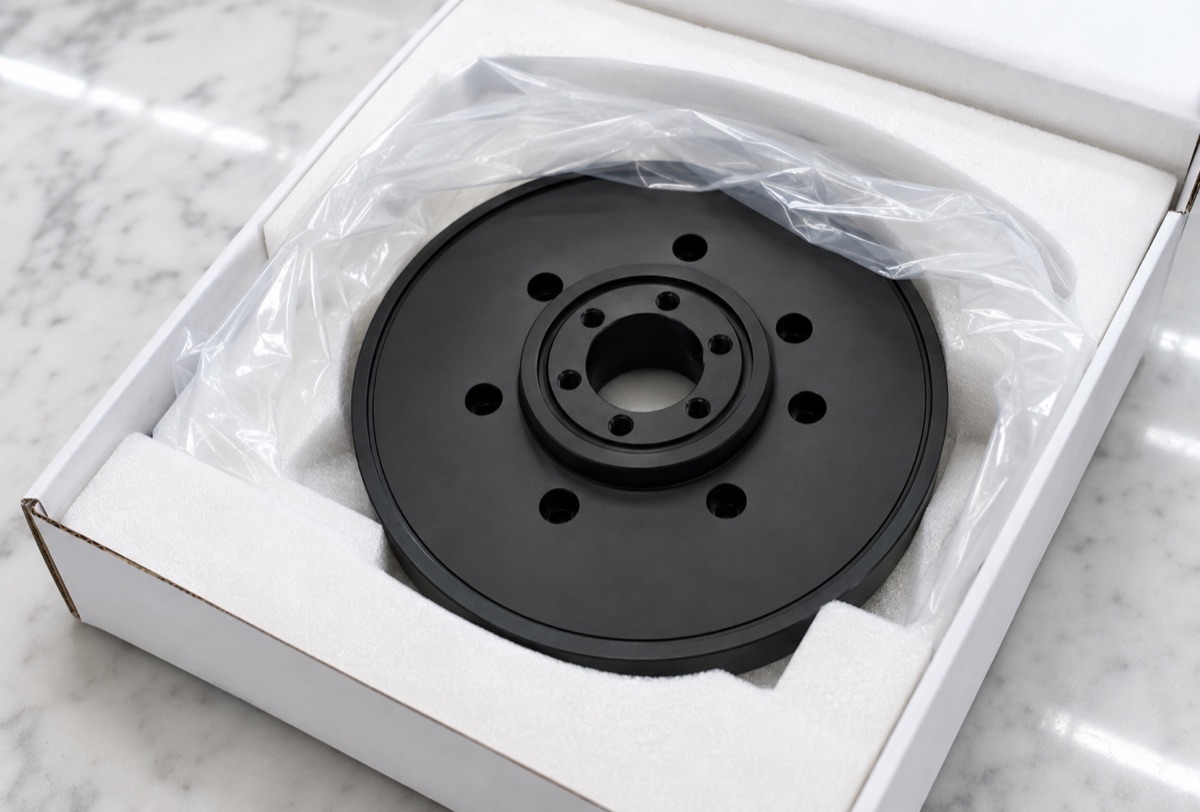
Individual support keeps the locating step, mounting face, hole edges and cosmetic anodized surface away from hard contact during shipment.
Case Summary
This case shows why a robot end flange should be controlled as one assembly interface. Stable delivery depends on the shared relationship between the center step, face and hole circles, followed by anodizing inspection and packaging that preserves those features.
FAQ
Which feature should be the primary datum on a robot end flange?
It depends on the mating design, but the mounting face and center axis commonly form the main datum system, with one hole or clocking feature controlling rotation.
Does black anodizing affect the center locating step?
Anodizing adds a coating and can change a close fit. Coating allowance, masking and the post-finish acceptance method should be defined before machining.
Why check the inner and outer hole circles together?
Their relative angle and position determine whether the connected components align. Checking each circle independently can miss an assembly-level clocking error.
How is the finished flange protected for shipment?
The locating step and mounting face are kept off hard surfaces with individual foam support, and the anodized finish is isolated from rubbing and contamination.
Ready to get a quote for your CNC machined parts?
Submit your engineering drawings to qiancj@oemach.com. We support prototype sampling and small-batch production with strict tolerance control.