
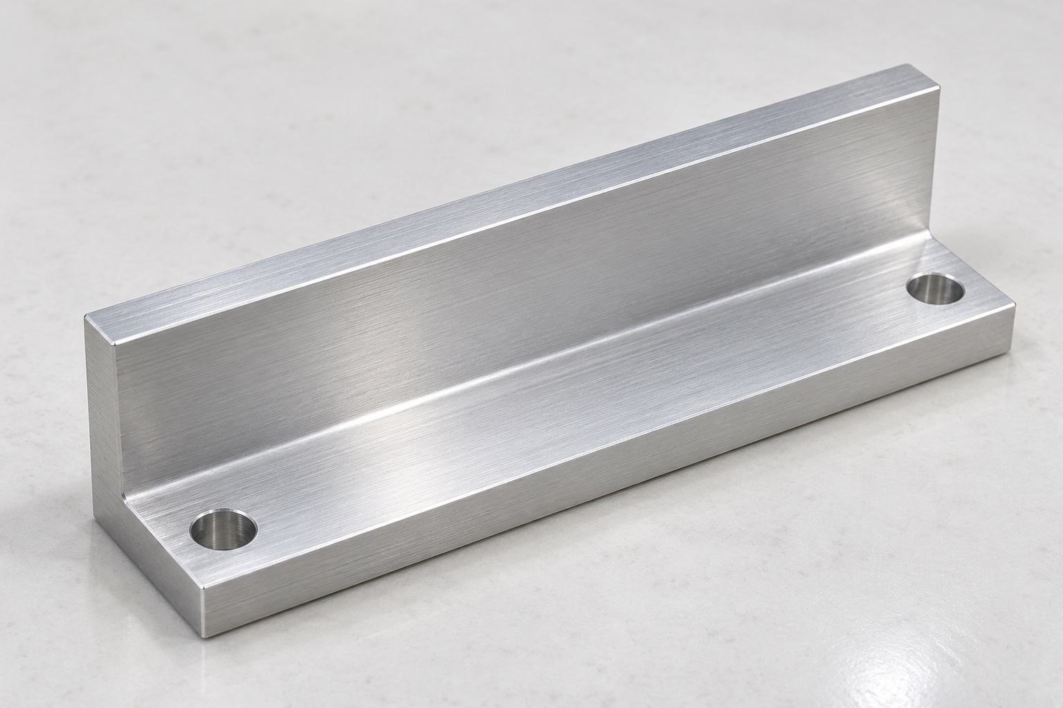
Representative proposed stepped contact jaw
This example considers a proposed one-piece 6061 aluminum clamp jaw for an equipment-side microplate mechanism in a medical analyzer. The illustrative geometry has a rectangular base, a raised straight rear wall, a lower front contact ledge and two vertical mounting through holes near the ends of that ledge. Actual plate contacts would follow approved assembly documents. This is a representative CNC workflow, not a customer delivery or measured sample. No achieved tolerance, holding force, repeated positioning, plate damage result, sterile status, medical certification or validated analytical performance is claimed for the proposed jaw.

Review the exact plate configuration
The proposed order would begin with controlled jaw geometry, exact plate and lid information, mounting arrangement and inspection deliverables. The review would identify permitted external contacts and distinguish the jaw from its actuator and opposing support. Missing contact or approach information would be clarified before costing and machining. A loose empty plate would not define every requirement. Component manufacture and optional assembly demonstrations would remain separate from clamping-force selection, repeated handling and analytical evaluations assigned to the responsible medical analyzer team for the actual mechanism and intended operating conditions.
Maintain the approved aluminum condition
The material package would specify the approved 6061 condition, stock form and required evidence. Blanks would retain lot identity through machining, final processing and shipment. Similar-looking offcuts would not automatically be equivalent. The supplier would review allowance and support near the upright wall and ledge before selecting the route. Substitutions would require authorization. Material evidence would support the purchased component scope only, not demonstrate friction, cleaning compatibility or sufficient holding performance for every microplate material and handling arrangement that could fit against an aluminum stepped contact jaw.
Establish mounting and contact references
Initial milling would establish the approved base and holding references needed to relate the ledge, upright face and two-hole mounting pattern. The sequence would consider material removal and fixture transfers so the stepped section remained related after release. Chips at locating contacts would be controlled before reorientation. The supplier would avoid accepting straightness or contact relationships only while the jaw was forced against a fixture. Intermediate checks could support process control, but final inspection would address the specified finished component in its agreed support and surface condition after relevant operations were complete.
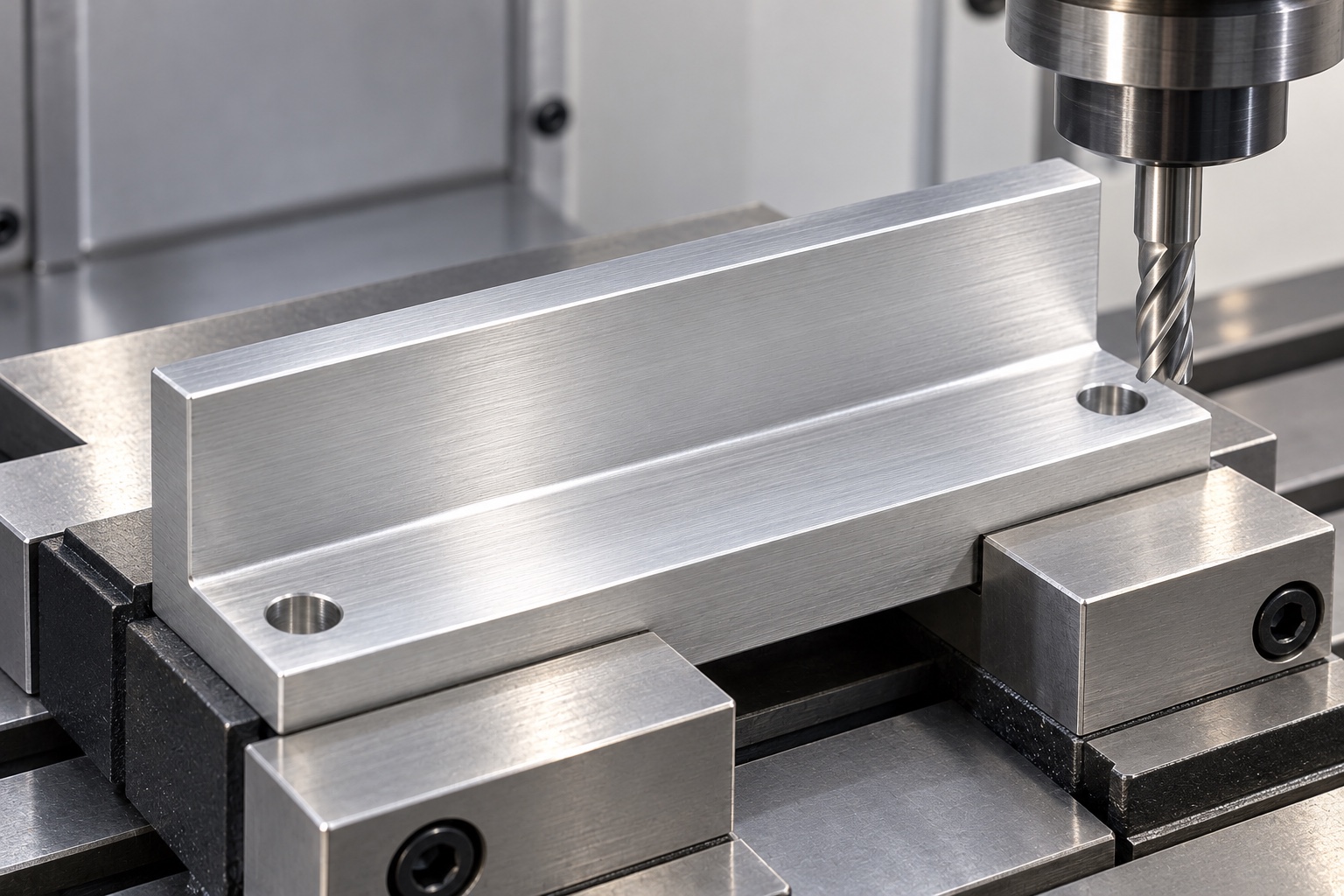
Machine the ledge and upright contact face
The contact features would follow the approved size, height, position and permitted transitions. Any internal corner radius or relief would be reviewed before production when it affected useful plate support. The supplier would not remove material until an unidentified plate appeared to slide freely. An authorized change would enter controlled documents. The contact ledge and wall would remain defined mechanical features, not evidence that the jaw could restrain every plate, preserve a seal, prevent specimen loss or achieve a particular positioning result in the complete medical analyzer mechanism.
Control mounting and entry clearances
The two through holes would follow released size, location and edge requirements relative to the functional references. Their role as clearance or locating features would remain explicit. Plate entry and removal envelopes would be reviewed with the actual mounting arrangement. The supplier would not add slots or substitute a lid to obtain a convenient demonstration. Model and drawing discrepancies would be resolved before machining decisions. Any approved modification would stay traceable so later production did not depend on a particular sample, operator adjustment or undocumented change to the jaw and its surrounding handling mechanism.
Preserve working boundaries during finishing
The finishing sequence would examine ledge boundaries, upright-wall ends and hole exits for attached material or unwanted sharp features. Removal would preserve useful contact rather than broadly polish or round the jaw. Cleaning and any final treatment would follow the purchased scope, with masking and relevant final-state checks agreed. Bare silver imagery would not prescribe an untreated delivery. A clean appearance would not establish quantified particles, non-damaging contact or sterile status. Accepted features would remain identifiable through later handling so the inspected jaw matched the condition required for the controlled assembly.
Plan accessible contact-based measurement
The proposed inspection plan would identify suitable methods for the ledge and upright-face relationships, base references and mounting holes. Support and final treatment would be recorded. Outside size and isolated hole diameters would be insufficient when other controlled contacts determined the interface. Inaccessible or ambiguous requirements would be clarified before production rather than replaced by easier measurements. A plate used for an optional trial would not automatically become a universal gauge. The component report would distinguish dimensional evidence from any observations of plate seating, entry or release within the actual mechanism.
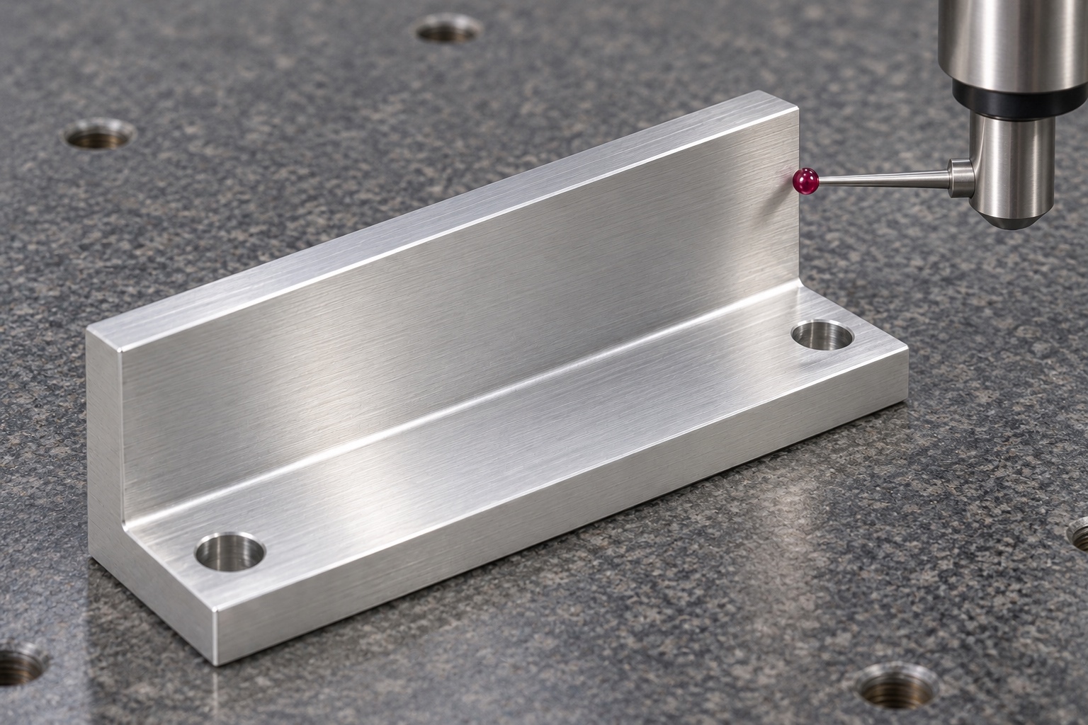
Prepare first-part records without measurements
The proposed report would identify drawing revision, material lot, numbered characteristics and agreed inspection methods. No numerical results are provided because this representative case has no manufactured sample or measurement record. Material and dimensional evidence would support component acceptance only. They would not demonstrate clamping force, repeated positioning, plate damage resistance or analytical accuracy. Nonconformances and approved changes would remain traceable. A jaw that could be bolted into a mechanism would not authorize omission of contact requirements or justify claims of successful medical sample handling without independently defined evaluation and supporting evidence.
Define an optional plate-handling observation
An agreed trial could examine seating, entry, removal and specified clearances using identified plate, lid, jaw and mechanism revisions. Procedure and any authorized contact insert would be recorded. Unexpected interference would be resolved before modifying parts or omitting accessories. Successful movement of an empty plate would not qualify loaded handling, repeated positioning, damage prevention, sample integrity or analyzer performance. Trial jaws would remain distinct from accepted production. Observations would enter controlled change records instead of becoming an informal manufacturing master or an approval for another plate variant and operating configuration.
Package contacts and handed variants separately
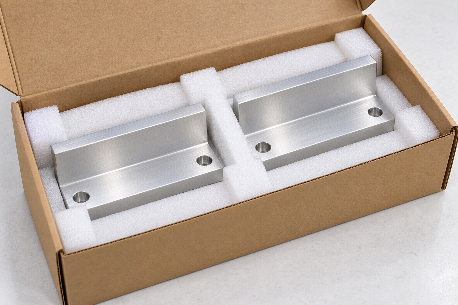
Finished jaws would be separated so neighboring edges, screws and packaging debris could not strike the ledge or upright wall. Support would protect the stepped shape without forcing it to bend. Packing materials would match the agreed cleaning scope without implying sterile delivery. Material lot, treatment, revision and inspection status would accompany the shipment. Receiving staff could distinguish released components from prototypes and any handed variants before assembly, avoiding an undocumented mixture of contact heights, mounting relationships or trial adjustments within a medical analyzer's otherwise controlled plate-handling mechanism and inspection baseline.
Preserve the plate-specific production baseline
The proposed baseline would retain geometry, approved plate contacts, mounting, material evidence, milling sequence, final processing and inspection scope. Repeat orders would review changed plate or lid variants, inserts, approach envelopes and mechanism travel before relying on earlier observations. Dimensional acceptance would remain separate from handling qualification. This case explains how a CNC supplier could document a stepped clamp jaw without inventing a customer delivery, achieved tolerance, holding-capacity result, positioning test or medical certification for an illustrative aluminum component and an unspecified complete medical analyzer installation and analytical workflow.
Manufacturer background reference: www.thermofisher.com.
FAQ
Is this an actual delivered clamp jaw?
No. It is a representative proposed machining example without a customer delivery or measured sample. No achieved tolerance, holding force, repeated positioning, sterile status, medical certification or analytical performance is presented as an actual result for the illustrated jaw.
What defines the permitted plate contacts?
The approved plate variant, lid and assembly documents define contact boundaries and clearances. The illustration does not authorize contact with wells or sealing film, nor does it establish a universal jaw geometry for different plate materials and handling mechanisms.
May the supplier choose actuator force?
Not from this example. Force, travel and permitted loading belong to the actual controlled mechanism. Component dimensions and a successful empty-plate fit should not be treated as sufficient evidence for safe clamping or handling under operating conditions.
What would first-part inspection show?
It would document agreed component characteristics with identified revision, material, methods and final condition. It would not independently establish holding force, transport positioning, plate damage resistance, specimen integrity or analytical accuracy of the complete medical instrument.
Can a plate-handling demonstration be included?
Yes, when plate, lid, mechanism, revisions, procedure and exact checks are agreed. Record the scope and keep mechanical observations separate from complete handling qualification, resolving unexpected contacts before authorizing changes to the jaw or assembly.
What should another production order review?
Review plate and lid variants, contacts, mounting, inserts, entry and removal envelopes, material and final treatment. Preserve revised documents rather than copying a hand-adjusted jaw or transferring another analyzer configuration's clamping and analytical performance claims.

tanghangyun@oemach.com