
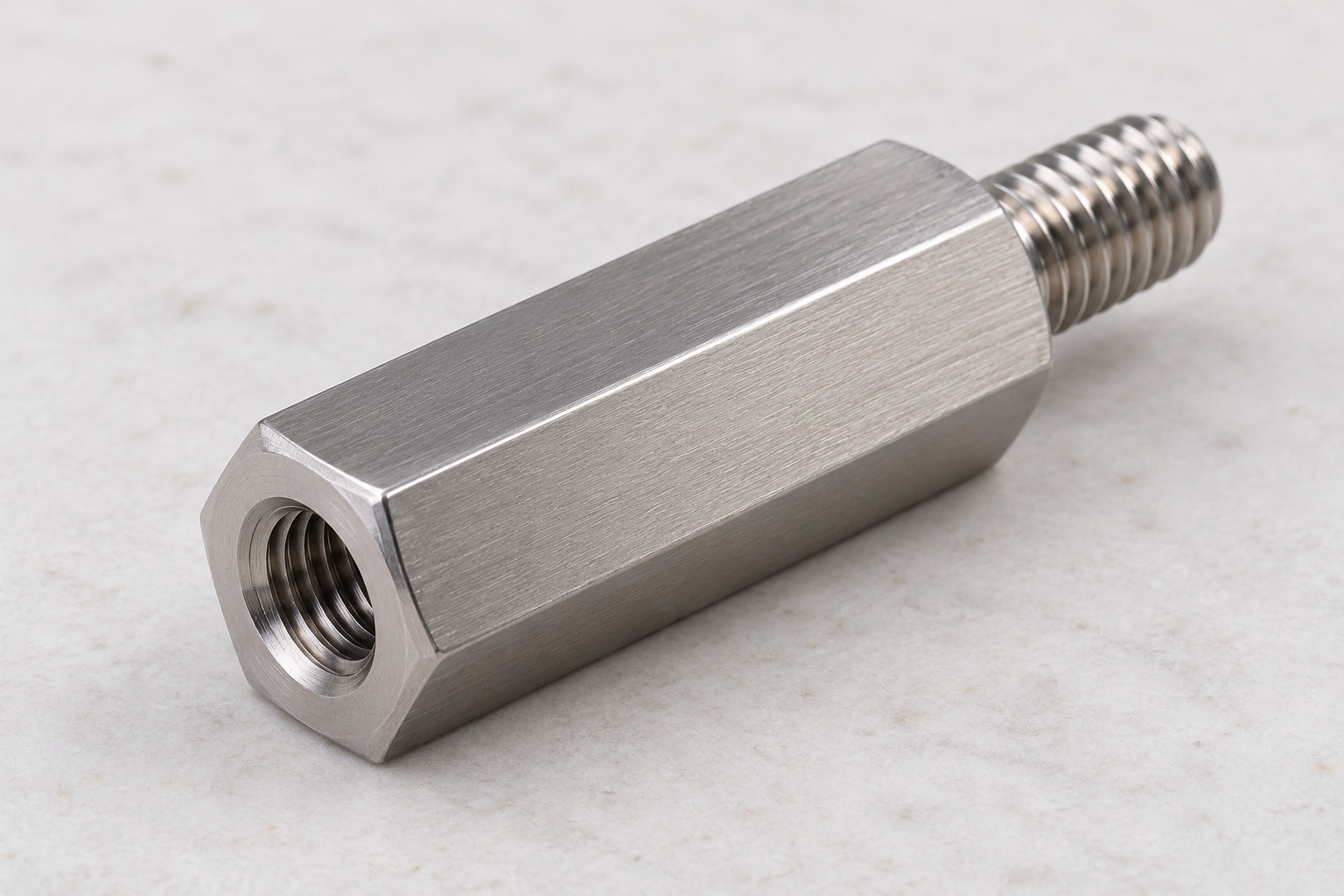
Representative proposed threaded separator
This example considers a proposed one-piece 316L stainless male-female hexagonal standoff for an equipment-side medical instrument assembly. It has a hexagonal seating body, one smaller external threaded stud and one coaxial blind female threaded opening at the opposite end. Actual threads and dimensions would follow approved documents. This is a representative CNC manufacturing workflow, not a customer delivery or measured joint. No achieved tolerance, clamp load, loosening resistance, fatigue result, electrical isolation, protective bonding, sterile status, medical certification or validated equipment safety outcome is claimed for this illustrative component.

Begin with the seated assembly definition
The proposed order would start with controlled model and drawing, mating parts, screw identities, seated stack and inspection requirements. The review would distinguish body length, stud projection, overall length and useful internal thread depth. Missing contacts or ambiguous thread definitions would be clarified before costing and manufacture. A loose screw would not define every requirement. Component machining and inspection would remain separate from optional seating demonstrations and independent joint, electrical or complete-equipment qualification assigned to the responsible medical instrument team for its actual assembly and intended service environment.
Maintain the specified 316L condition
The material package would identify approved grade, condition, stock form and evidence. Cut blanks would remain linked to the lot through machining, final processing and shipment. A catalog product in 303 stainless would provide category background only, not authorize substitution or establish identical properties. The supplier would review allowance and holding contacts before choosing the route. Any substitution would require approval. Material documents would support component identity, not demonstrate corrosion performance in a specified cleaner, joint strength, electrical behavior or medical certification for every installed arrangement using a similar hexagonal separator.
Relate the body to both threaded ends
The manufacturing route would preserve the relationship between seating faces, body and coaxial features through turning, drilling, thread production and any operation on the flats. Approved hexagonal stock or machined flats would be selected deliberately. Holding would protect accepted surfaces rather than rely on gripping a finished thread. Chips at locating contacts would be controlled before transfers. Intermediate checks could support the route, but final acceptance would address the finished component in its agreed condition rather than assuming that separately acceptable ends guaranteed the complete seating stack and axial relationships.
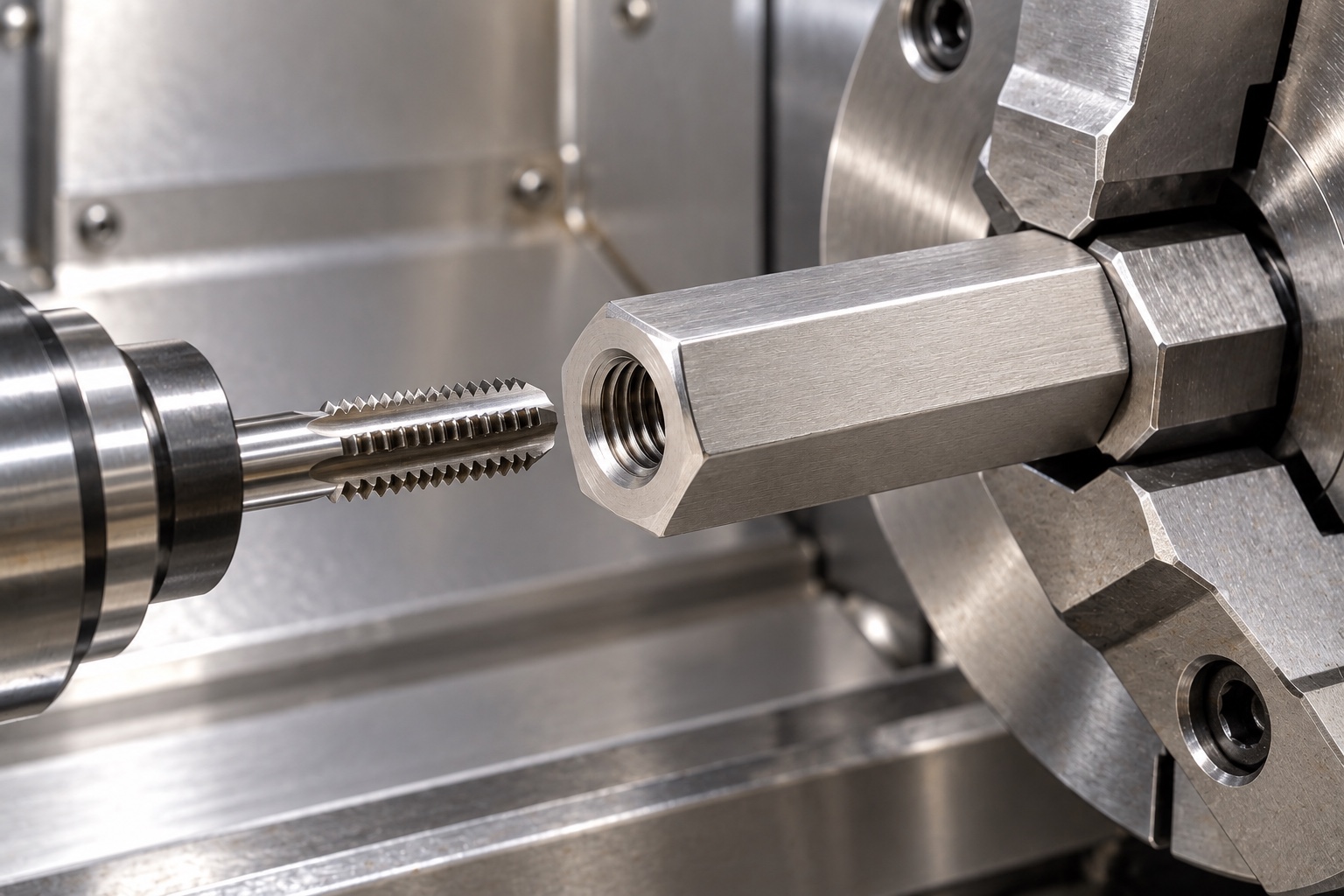
Machine the projecting external thread
The external stud would follow released thread identity, projection, runout and shoulder requirements. Tool access and permitted transitions would be reviewed before production. The supplier would not shorten the stud until an unidentified panel assembly could be tightened. Any authorized change would enter controlled manufacturing and inspection documents. The stud would remain a defined fastening feature, not evidence of a tested clamp load or fatigue result. Its conformity would be assessed alongside the seating body and female end rather than treated as sufficient proof that the complete spacer matched the actual medical equipment assembly.
Define the blind female end explicitly
Drilling and internal threading would follow the approved useful depth, thread requirements and permitted incomplete regions. Mating-screw projection and required clearance would be reviewed from controlled documents without inventing universal engagement values. The supplier would not deepen the hole or remove a seat to make a trial screw appear flush. Conflicts would be clarified before manufacture. Accepted modifications would remain traceable so future orders did not depend on a particular screw sample, changed panel thickness or undocumented adjustment that could hide bottoming rather than establish the correct installed contact stack.
Preserve seats during finishing and cleaning
The finishing sequence would examine thread starts, runouts, blind-hole entry, hexagon edges and seating shoulders for attached material or unwanted sharp features. Removal would preserve useful thread and contact geometry. Cleaning and any approved passivation or other treatment would follow the purchase scope, with relevant final-state checks. A bright surface would not establish measured corrosion resistance, sterile supply or a qualified locking function. Residue inside the female end would be addressed without concealing damaged threads or introducing an uncontrolled compound before dimensional inspection and protected shipment.
Assign a method to each characteristic
The proposed inspection plan would separately identify thread conformity, useful internal depth, stud projection, body seating length and specified reference relationships. Gauge access, support and final treatment would be recorded. A favorable thread gauge or hand assembly would not answer every requirement. Ambiguous dimensions would be resolved before production rather than replaced by a convenient screw sample. The report would state what each method checked so component acceptance did not imply a measured clamp load, complete joint qualification or approval of another body length and screw combination that merely appeared similar.
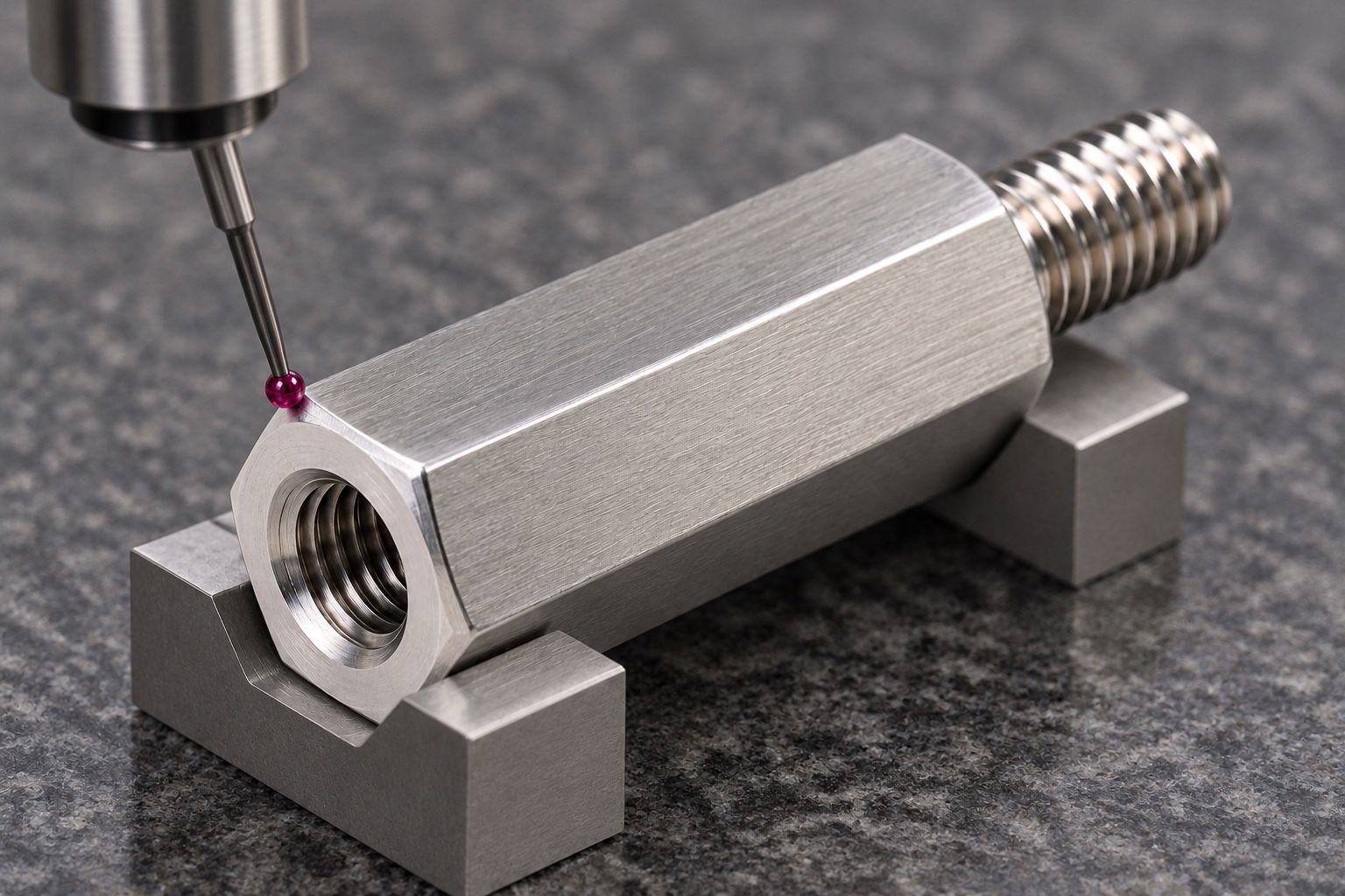
Prepare first-part records without invented results
The proposed report would identify drawing revision, material lot, numbered characteristics and agreed inspection methods. No numerical measurements are provided because this representative example has no manufactured sample or measurement record. Material and dimensional evidence would support only the purchased component scope. They would not establish loosening resistance, fatigue, electrical isolation or protective bonding. Any nonconformance and approved revision would remain traceable. A standoff that could be screwed between two panels would not authorize omission of a useful-depth check or justify claiming that medical equipment safety had been validated.
Define an optional seating trial
An agreed trial could examine engagement, shoulder seating and tool access using identified standoff, screw and mating-component revisions. Installation procedure, surface treatment and any authorized locking method would be recorded. Unexpected gaps would be investigated before changing depth, body length or hardware. Successful hand assembly would not qualify torque, clamp load, loosening, fatigue or electrical safety. Trial components would remain distinguishable from accepted production. Observations would enter controlled records instead of becoming an informal production master or approval for another panel stack and medical instrument configuration introduced in a later order.
Separate studs and female openings in packaging
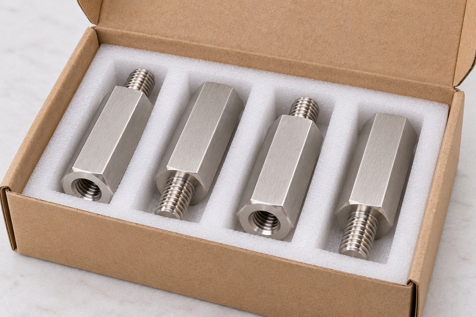
Finished standoffs would be individually separated so projecting threads could not strike accepted seats and loose hardware could not enter female openings. Protective materials would match the agreed cleaning scope without implying sterile delivery. Material, condition, lot, thread variant, revision and inspection status would remain identifiable. Receiving staff could distinguish released parts from prototypes and visually similar spacers with different seating lengths, blind depths or thread identities before assembly or maintenance stock was populated, preserving the controlled baseline for installation and any independent joint or equipment-level evaluations.
Preserve the configuration-specific baseline
The proposed baseline would retain controlled geometry, mating parts, both threads, useful depth, material evidence, machining sequence, final processing and inspection scope. Repeat orders would review changed screw lengths, panel stack, treatments and locking methods before relying on earlier observations. Component acceptance would remain separate from joint and equipment qualification. This case explains how a CNC supplier could document a custom threaded separator without inventing a customer delivery, achieved tolerance, clamp-load result, electrical safety outcome or medical certification for an illustrative 316L standoff and an unspecified installed medical instrument assembly.
Manufacturer background reference: www.wdscomponents.com.
FAQ
Is this an actual delivered or qualified standoff?
No. It is a representative proposed CNC example without a customer delivery or measured sample. No achieved tolerance, clamp load, fatigue result, electrical safety function or medical certification is presented as an actual result for the illustrative separator.
What defines the two thread interfaces?
The controlled drawing and actual mating components define both thread identities, useful engagement, stud projection and blind depth. A similar screw entering an opening does not establish complete compatibility or authorize changing the seating stack.
Can 303 replace the proposed 316L material?
Not automatically. The catalog reference describes a different material and supplies category background only. Any substitution requires design approval and appropriate evidence for the actual part, installation, environment and purchased inspection scope.
What would first-part evidence establish?
It would document the agreed component characteristics with identified revision, material, methods and final condition. It would not independently establish clamp load, loosening resistance, fatigue, electrical isolation, protective bonding or medical equipment safety.
May a seating demonstration be included?
Yes, when mating parts, screws, revisions, installation method and exact checks are agreed. Record observations separately from joint and electrical qualification, and investigate gaps or bottoming before authorizing changes to the component or assembly.
What needs review before another production batch?
Review threads, seating length, stud projection, useful female depth, mating hardware, stack, material, final treatment and locking method. Preserve controlled revisions rather than recreating a hand-adjusted spacer or transferring another fastening arrangement's performance claims.

tanghangyun@oemach.com