
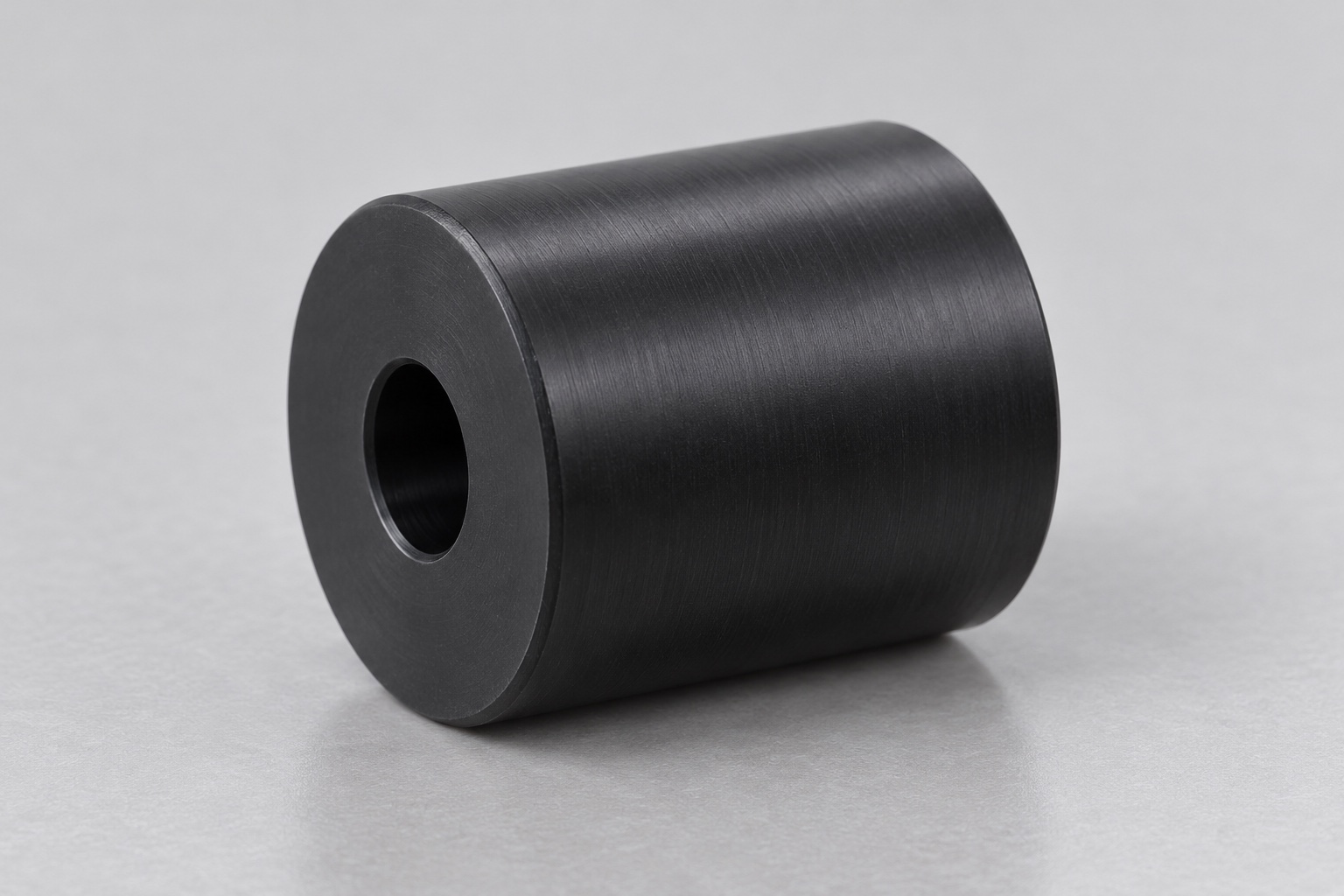
Representative proposed tray support roller
This example considers a proposed one-piece black POM roller for an equipment-side tray mechanism in a medical laboratory instrument. Its illustrative geometry is a smooth cylindrical barrel with one central through bore and two flat annular end faces. It has no illustrated bearing, tread, groove or internal thread. This is a representative CNC turning workflow, not a customer delivery or measured production sample. No achieved tolerance, rolling resistance, wear life, transport accuracy, specimen integrity, sterile status, medical certification or validated equipment safety result is claimed for this proposed component.

Review the complete rolling interface
The proposed order would start with the controlled roller model and drawing, approved tray contact, exact axle, retention arrangement and inspection requirements. The review would clarify the intended bore role and the running width used by the tray. A loose axle or photograph would not define all acceptance conditions. Missing interfaces would be resolved before manufacture. Component turning and inspection would remain separate from optional assembly demonstrations and independent transport, wear or sample-handling evaluations assigned to the responsible laboratory equipment team for its actual mechanism and intended operating conditions.
Keep polymer grade and stock traceable
The material order would identify the approved POM grade, stock form and required evidence. Cut blanks would remain linked to the material lot through turning, finishing and shipment. Black color alone would not establish equivalence to another plastic or a modified acetal grade. The supplier would review machining allowance and holding regions before selecting the route. Any substitution would require authorization. Material documentation would support component identity only, not establish cleaning compatibility, electrical behavior, biocompatibility or a measured service life for every tray arrangement and laboratory environment that might use a small roller.
Plan bore and running references together
The turning sequence would consider how the bore and outside running surface would be related through initial holding, finishing and any reverse operation. Clamping would avoid excessive compression of the annular section. Chips at holding contacts would be controlled before transfers. Intermediate checks could reveal problems, but final acceptance would address the roller after release in the agreed support and conditioning state. The supplier would not assume that a dimension obtained in the chuck represented the final component or replace a required relationship with an easier isolated outside diameter measurement.
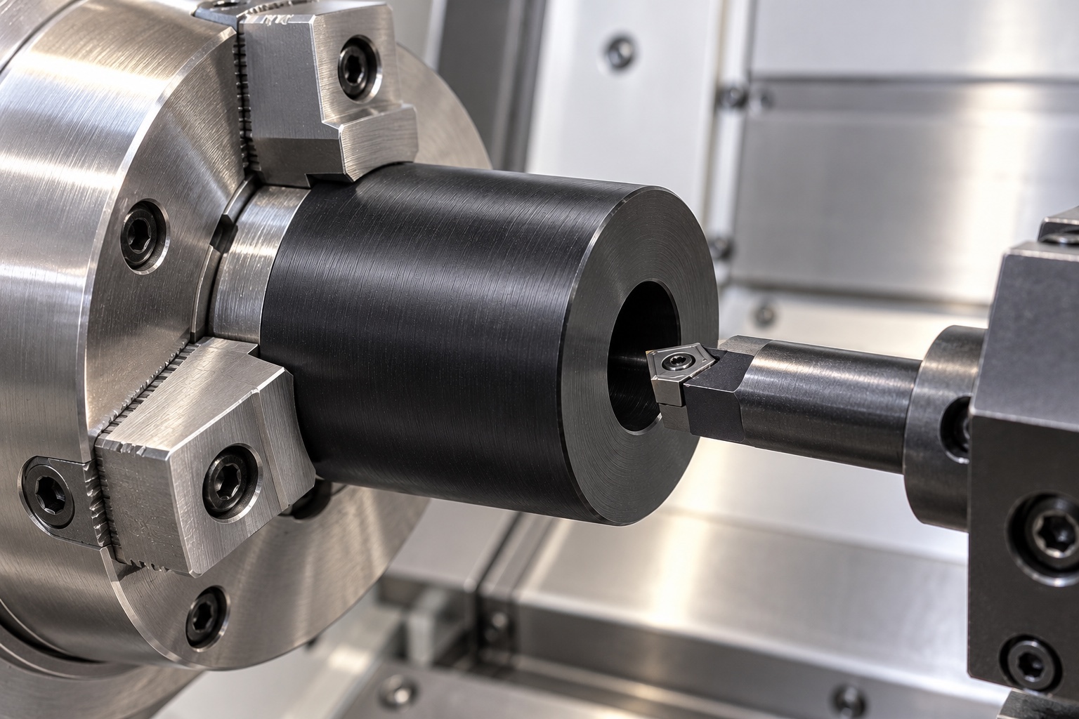
Finish the useful cylindrical surface
The running diameter, useful width and required relationship to the bore would follow the approved drawing and tray contact definition. Tool access, surface requirements and permitted edge transitions would be agreed before production. The supplier would not add a crown, groove or tread because a different transport wheel used one. Any authorized geometry change would enter controlled documents. A smooth surface would remain a mechanical feature, not evidence of a tested coefficient of friction, load rating, wear result or accurate movement of a sample tray in the complete laboratory instrument.
Control bore and axial boundaries
The central through bore and two end faces would follow the released dimensions, relationships and edge requirements. The actual axle and retention arrangement would be reviewed without silently assuming a bearing fit. End clearance would not be created by shortening the roller until an unidentified shaft assembly turned freely. Model and drawing discrepancies would be clarified before machining decisions. Approved modifications would remain traceable so later batches did not depend on a trial washer stack, changed axle, operator preference or undocumented adjustment to the roller and its neighboring support structure.
Finish edges without changing the working width
The finishing sequence would examine bore exits and outside boundaries for attached material or unwanted sharp features. Removal would preserve useful rolling width and bore geometry rather than broadly round the ends or enlarge the openings. Cleaning would follow the purchased polymer-compatible scope. A visually clean part would not establish quantified particles, validated decontamination or sterile delivery. Any later treatment would require approval and relevant final-state checks. Accepted surfaces would be protected during handling so finishing did not conceal damage or introduce an unapproved condition before the specified first-part inspection.
Agree the unloaded measurement condition
The inspection plan would identify methods for running diameter, bore size, useful length and the drawing's specified geometric relationships. Support, conditioning and relevant measurement contact would be recorded. A single caliper reading or an axle passing through the bore would not cover all controlled characteristics. Ambiguous or inaccessible requirements would be resolved before manufacture. The supplier and purchaser would agree how the finished roller was checked rather than accepting results taken only under manufacturing restraint or substituting a favorable rotation demonstration for required dimensional evidence in the agreed final component state.
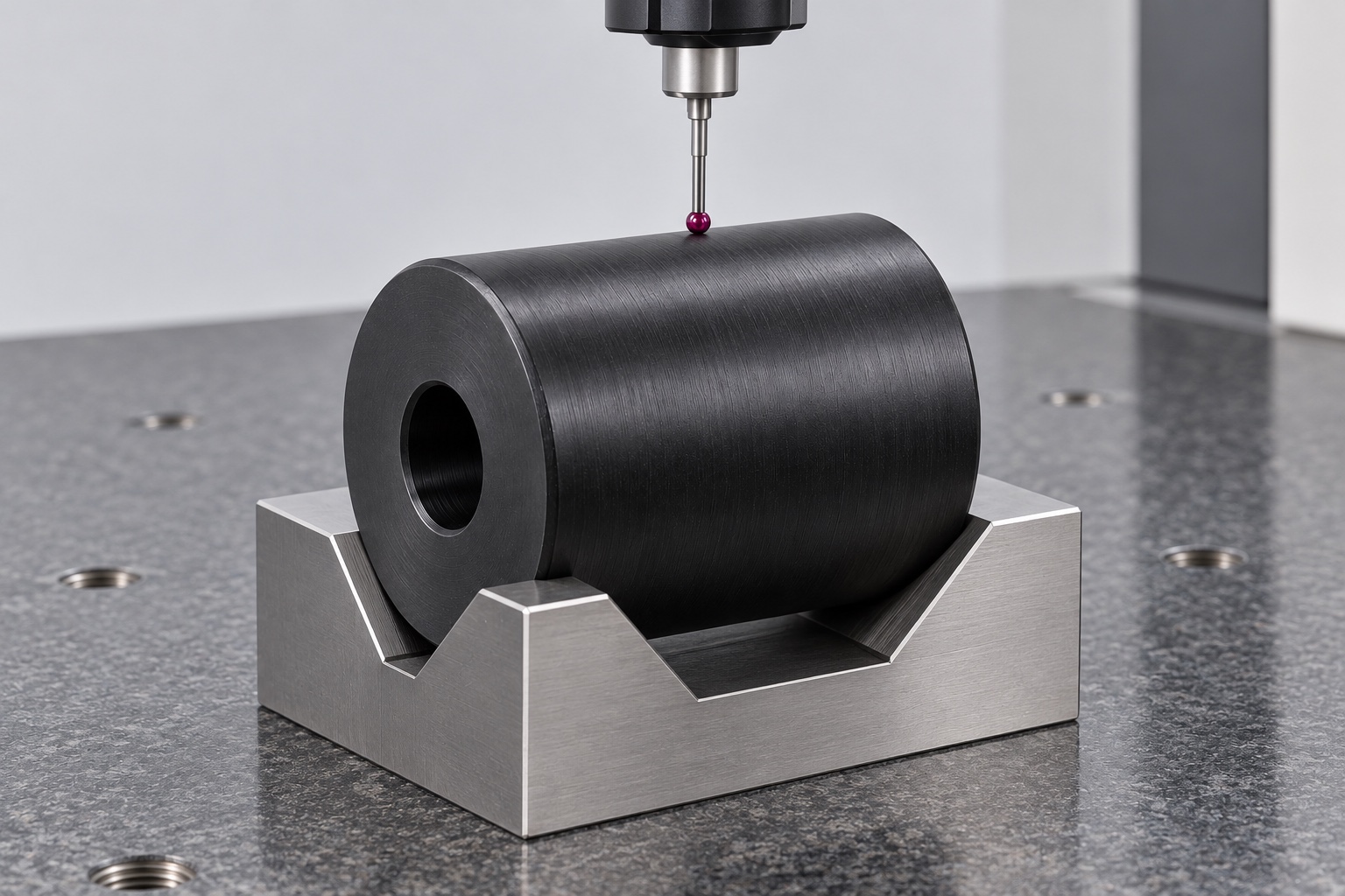
Prepare traceable first-part records
The proposed report would identify drawing revision, material lot, numbered requirements and agreed inspection methods. No numerical measurements are supplied because this illustrative case has no manufactured sample or inspection record. Component evidence would not demonstrate wear life, transport repeatability or sample integrity. Any nonconformance and approved change would remain traceable. A roller that assembled onto an axle would not authorize omission of a bore relationship or end-face requirement. The final record would distinguish dimensional conformity from optional assembly observations and any independent evaluation of the complete medical laboratory transport system.
Define a limited assembly demonstration
An agreed trial could examine installation, end clearance and rotation with identified axle, retaining hardware and tray revisions. The presence of the tray and actual test conditions would be documented. Unexpected resistance would be investigated before changing the bore, shortening the body or introducing lubricant. Successful hand rotation would not qualify loaded rolling resistance, service life, transport positioning or specimen handling. Trial rollers would remain distinguishable from accepted production. Observations would enter controlled change records rather than becoming an informal gauge or an undocumented approval for another laboratory mechanism and operating environment.
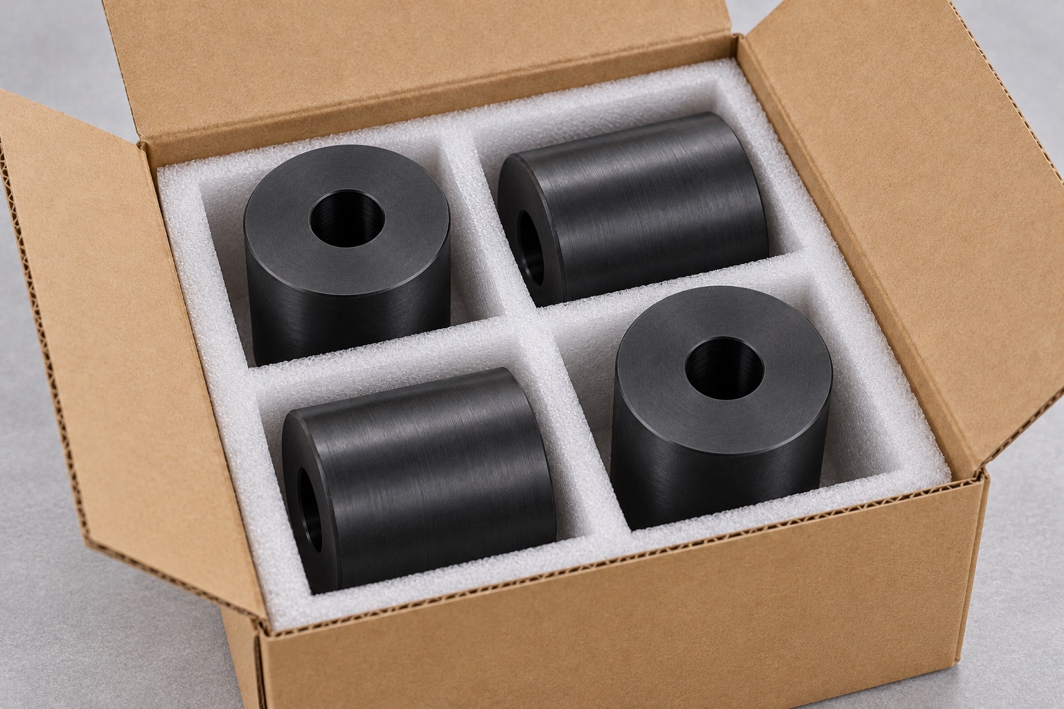
Package bore and running surfaces separately
Finished rollers would be individually separated so neighboring edges, shafts and debris could not strike the running surfaces or enter the bores. Packaging would avoid unnecessary compression and match the agreed cleaning scope. Protective bags would not imply sterile supply. Grade, material lot, revision and inspection status would stay with the shipment. Receiving staff could distinguish released rollers from trial components and visually similar variants with different bore sizes, lengths or polymer identities before they entered equipment assembly or service stock, preserving the controlled mechanical baseline for later installation and independent evaluation.
Preserve a mechanism-specific repeat baseline
The proposed baseline would retain controlled geometry, tray and axle interfaces, material identity, machining sequence, edge requirements, final condition and inspection scope. Repeat orders would review changed contacts, retention, load, cleaning or lubrication before relying on previous observations. Component acceptance would remain separate from transport qualification. This representative case explains how a CNC supplier could document a polymer rolling interface without inventing a customer delivery, achieved tolerance, wear test, sample-integrity outcome or medical certification for an illustrative black roller and an unspecified complete laboratory instrument or sample-handling process.
Manufacturer background reference: www.ensingerplastics.com.
FAQ
Is this a tested production roller?
No. It is a representative proposed turning example without an actual delivery, manufactured sample or measured performance. No achieved tolerance, wear life, rolling resistance, transport accuracy or medical certification is presented as an actual result for the illustrated roller.
What determines the bore fit?
The approved axle and assembly documents define the bore's role and requirements. A central opening does not automatically specify a bearing fit, direct sliding interface, lubricant or retention method, and an unrelated axle sample cannot replace those controlled documents.
Can the supplier add a crown or tread?
Only after authorization if the controlled design changes. Running profile and contact width belong to the actual tray mechanism. Features copied from another wheel may alter the interface and should not be introduced to obtain a convenient demonstration.
What would first-part inspection cover?
It would document agreed dimensions and relationships with identified revision, material, methods and final condition. It would not independently establish rolling resistance, wear, transport accuracy, sample integrity or the safety of the complete laboratory instrument.
May rotation be demonstrated during a trial?
Yes, when axle, retention, tray, revisions and exact checks are agreed. Record whether the tray is installed and separate mechanical observations from loaded performance, wear and sample-handling qualification of the actual complete mechanism.
What needs review before repeating manufacture?
Review tray contact, axle, bore, useful length, retention, polymer grade, load, cleaning and lubrication. Preserve controlled revisions rather than duplicating a hand-adjusted roller or transferring another transport mechanism's wear and positioning claims to this representative component.

tanghangyun@oemach.com