
A sensor substitute flange is compact, but its positioning features are densely connected. During robot debugging or replacement installation, the customer needs stable location, smooth fastening and sufficient clearance around the neighboring module.
This 6061 aluminum flange combines a precision center bore, stepped faces, an inner M4 pattern and an outer mounting pattern. OEMach planned the work around the relationship between both sides of the interface, then protected that relationship through black anodizing and final inspection.
Project Snapshot
| Item | Project detail |
|---|---|
| Application | Robot joint sensor installation, substitute positioning and debugging |
| Material and finish | 6061 aluminum, 180-grit blasting and black anodizing |
| Key features | Precision center bore, stepped face, inner M4 threaded pattern and outer mounting holes |
| Control focus | Datum closure, bore-to-pattern relationship, angular position, threads, edge protection and anodized appearance |
Treat A Small Flange As A Positioning Component
The first review determines whether the center bore is the primary locator and which side of the assembly uses each hole pattern. The inner and outer patterns may look evenly distributed, but their angular relationship must match the two mating interfaces.
This functional review prevents the drawing from being reduced to a list of diameters. The stepped face, bore axis, threaded pattern and outer holes must remain in one consistent datum system.
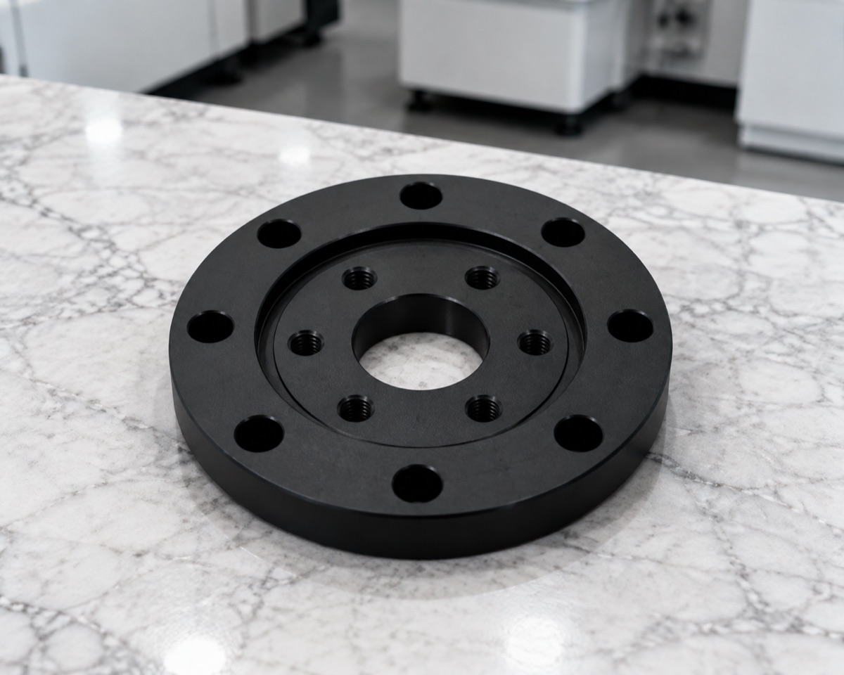
The center bore, stepped face, inner threaded pattern and outer mounting pattern form one compact positioning interface.
Dense Features Leave Little Rework Margin
The center bore, threads and outer holes sit close together, leaving limited material between features. A burr, tight thread or angular shift can stop the customer's debugging work even when the part is visually small and simple.
OEMach establishes the face and center bore first, then machines the inner and outer patterns from the same datum closure wherever practical. Fewer unrelated setups reduce angular accumulation and make the hole-pattern relationship easier to verify.
Protect The Center Bore And Stepped Face
The center bore and stepped face need a clear functional boundary. Deburring should be consistent but light, because excessive edge breaking can reduce the effective contact area or alter the locating entry.
Before anodizing, the part is checked for chips, burrs and thread cleanliness. After treatment, the review covers color consistency, residue, thread gauges, hole mouths and the condition of the center bore.
Inspect The Bore And Both Hole Patterns Together
First-article inspection includes center-bore size, face flatness, step height, M4 thread gauges, outer-hole position, chamfers and black appearance. The most important result is the relationship among these features, not only whether each hole passes separately.
Probe measurement can establish concentric and angular position from one datum strategy. This supports a faster assembly decision and reduces the chance that the customer discovers a pattern mismatch during installation.
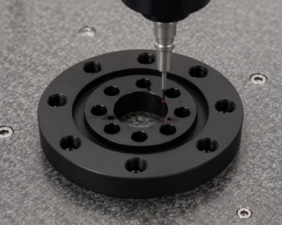
Inspection links the bore, inner M4 pattern, outer holes and stepped face instead of accepting each feature independently.
Schedule And Packaging Follow The Debugging Window
Prototype lead time for this 6061 black-anodized flange is generally evaluated at 5 to 8 working days, with small batches planned at approximately 8 to 12 working days. When the debugging window is tight, first-article inspection feedback can be prioritized before the remaining quantity.
Each flange is located separately in foam, with the front and back faces protected from rubbing. The center bore and threaded holes remain clean, while the anodized surface is isolated from impact and loose particles during shipment.
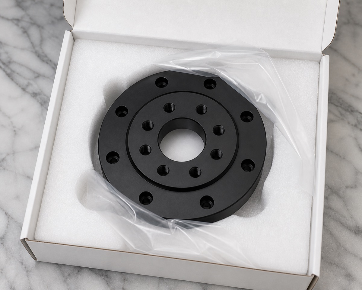
Individual location prevents face-to-face rubbing and keeps particles away from the center bore and threaded holes.
Case Summary
This sensor substitute flange case shows why a small part can require a detailed control plan. Datum planning, one-closure hole-pattern machining, anodizing protection and relationship-based inspection help the flange enter robot debugging without avoidable fitting work.
FAQ
Why is the center bore critical on a sensor substitute flange?
It often establishes the main locating axis. If its position or relationship to the stepped face and hole patterns drifts, both mating interfaces can become difficult to assemble.
Should the inner and outer hole patterns be inspected separately?
Their individual sizes should pass, but concentric and angular relationships should also be verified in one datum system because the two patterns serve connected interfaces.
What needs to be rechecked after black anodizing?
Typical checks include the center bore, thread gauges, hole mouths, residue, color consistency, contact faces and any dimensions affected by the coating strategy.
Ready to get a quote for your CNC machined parts?
Submit your engineering drawings to qiancj@oemach.com. We support prototype sampling and small-batch production with strict tolerance control.