
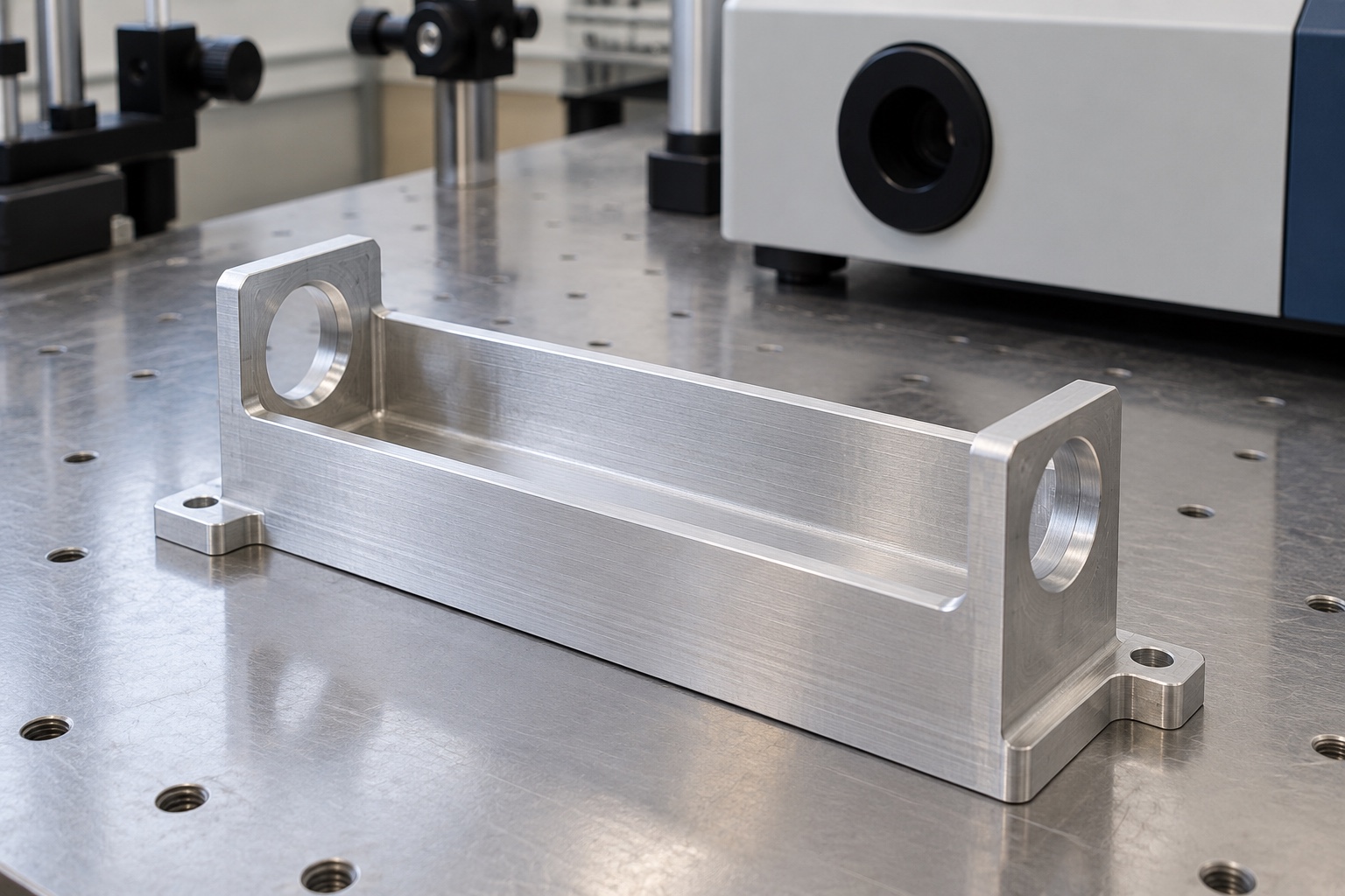
A representative proposed optical body
This example considers a proposed one-piece 6061 aluminum optical baffle body with an open top, internal channel, circular end apertures and external mounting features for diagnostic equipment. It illustrates a possible manufacturing workflow, not an actual customer delivery or validated optical system. The images show geometry concepts rather than achieved dimensions or performance results. Final internal geometry, material condition, cover interfaces and surface process would need approved project documents. No stray-light rejection, detector accuracy, achieved tolerance, certification or validated medical-device performance is claimed for the proposed component.

Review aperture and mounting documents
The proposed order would begin with controlled component drawings and model, approved aperture references, mating optics information and the actual cover arrangement. The supplier would distinguish functional openings from assembly access and cosmetic regions. Missing information about internal corners, cover clearance or measurement access would be returned for written clarification before costing and routing were finalized. A detached optical sample would not replace the complete interface package. The purchase scope would distinguish dimensional manufacture, optional assembly trials and any separate optical or equipment-level evaluation assigned to the responsible design program.
Preserve aluminum grade and stock condition
The stock order would identify the approved 6061 material, condition, form and documentation. Material-lot identity would remain with blanks through machining, final treatment and packaging. A similar-looking aluminum part would not establish equivalence. The supplier would review machining allowance and support needs for the elongated open cavity. Any proposed substitution or stock change would require authorization before production. The material designation would remain a design input rather than a general assertion of optical suitability, cleaning compatibility, corrosion performance or medical certification for the complete diagnostic instrument.
Establish stable functional references
Early machining would establish the mounting plane and locating references needed for later cavity and aperture operations. Workholding would provide broad support without forcing thin walls into an apparently correct position. Chips at fixture contacts would be controlled before each reference transfer. The route would consider how internal material removal changes the part's stiffness. Intermediate checks could confirm the sequence but would not replace final acceptance. The intended result would be repeatable geometry in the specified condition, not a single correct-looking sample held in shape by an excessive fixture load.
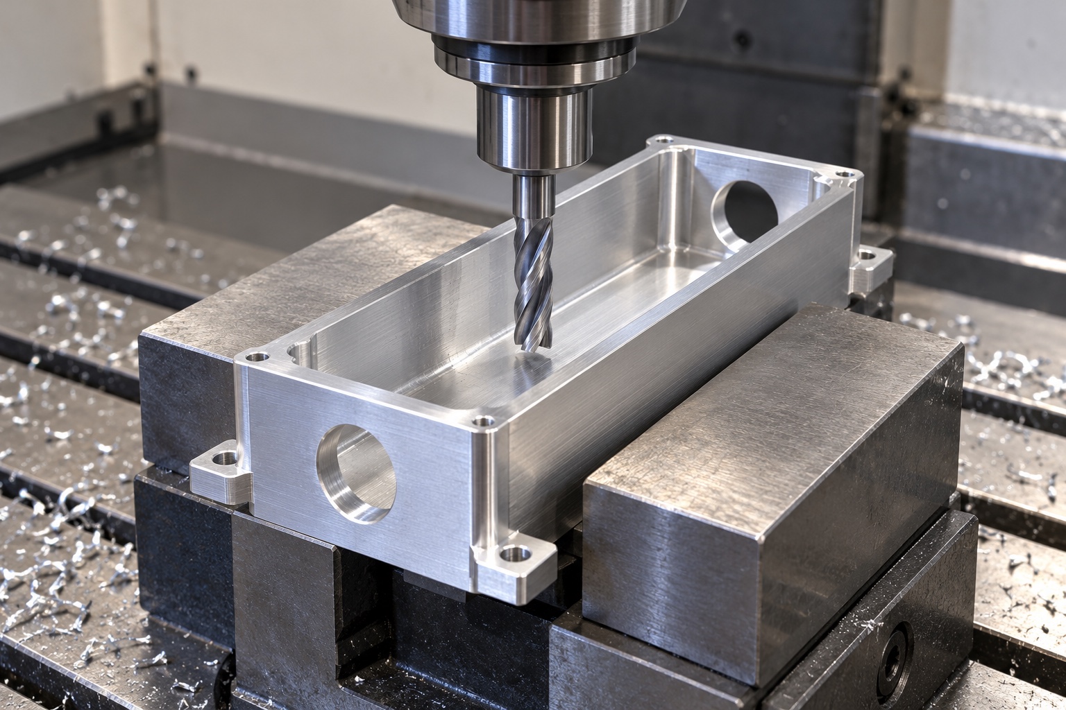
Machine the channel and approved transitions
The open cavity would be produced against the controlled geometry, including specified wall relationships and internal transitions. Cutter access and corner radii would be reviewed before manufacture so they did not become undocumented deviations. A proposed relief would need design approval if it changed the internal envelope. The supplier would not remove material informally to fit an unapproved optical sample. Any accepted revision would enter the model, drawing and inspection plan, preserving the difference between manufacturability advice and an authorized change to the diagnostic instrument's optical and mechanical interface.
Produce apertures from installation references
The end apertures would be related to the mounting references and each other as defined by the drawing. The process would preserve those relationships through required setups rather than inspecting only two convenient diameters. The supplier would not infer acceptable alignment from a light beam photograph or a loose part inserted by hand. Method selection would depend on actual geometry, access and approved requirements. A dimensional report would address the completed aperture configuration, while any optical evaluation would remain a separately defined activity with its own assembly, conditions and acceptance criteria.
Complete cover and fastener interfaces
Mounting tabs, cover contacts and any specified fastener features would follow the approved assembly arrangement. The review would include tool access, screw-head seating and clearances to neighboring components. Model and drawing discrepancies would be resolved before production decisions. The supplier would examine hole exits and hidden contact regions rather than only visible exterior surfaces. An accepted prototype alteration would be documented before entering repeat manufacture. An operator instruction to scrape a cover or force a part into place would not constitute a controlled production interface or an adequate acceptance record.
Apply only the approved surface condition
If the design required a dark finish or another treatment, masking, documentation and final-condition checks would be agreed beforehand. The bare-metal illustrations do not specify the final optical coating. Contact surfaces or apertures would not receive an unapproved treatment simply to create uniform appearance. Edge finishing would preserve the required geometry. The example makes no claim that color demonstrates optical absorption, cleanliness or chemical compatibility. A changed process would be reviewed against the accepted configuration rather than absorbed into a supplier preference that could alter the component interface or supporting evidence.
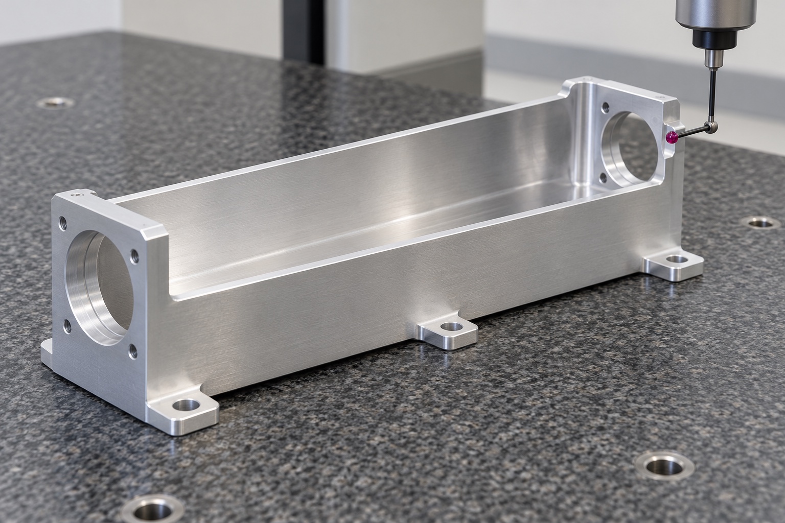
Prepare traceable first-part evidence
The report would identify the drawing revision, material lot and numbered requirements, including relevant apertures, cavity geometry and mounting relationships. It would record inspection methods, support conditions and the final treatment state. No numerical results are provided because this representative example has no manufactured sample or inspection record. Material and dimensional evidence could support acceptance within the purchased component scope. It would not establish light rejection, photometric accuracy or clinical suitability without the responsible program's separate evaluation of the complete installed optical configuration and its operating conditions.
Define an optional assembly demonstration
A limited trial could check insertion, cover seating and agreed access or clearances with identified approved components. The procedure would record the body, cover and mating revisions. It would not be described as optical qualification unless that evaluation were independently defined and performed. Unexpected contact would be documented before changing the cavity, aperture or cover. A hand-fitted sample would not become the production standard without approved documents and corresponding inspection. Results would not automatically apply to another coating, detector or illumination arrangement that happened to use a similar housing outline.
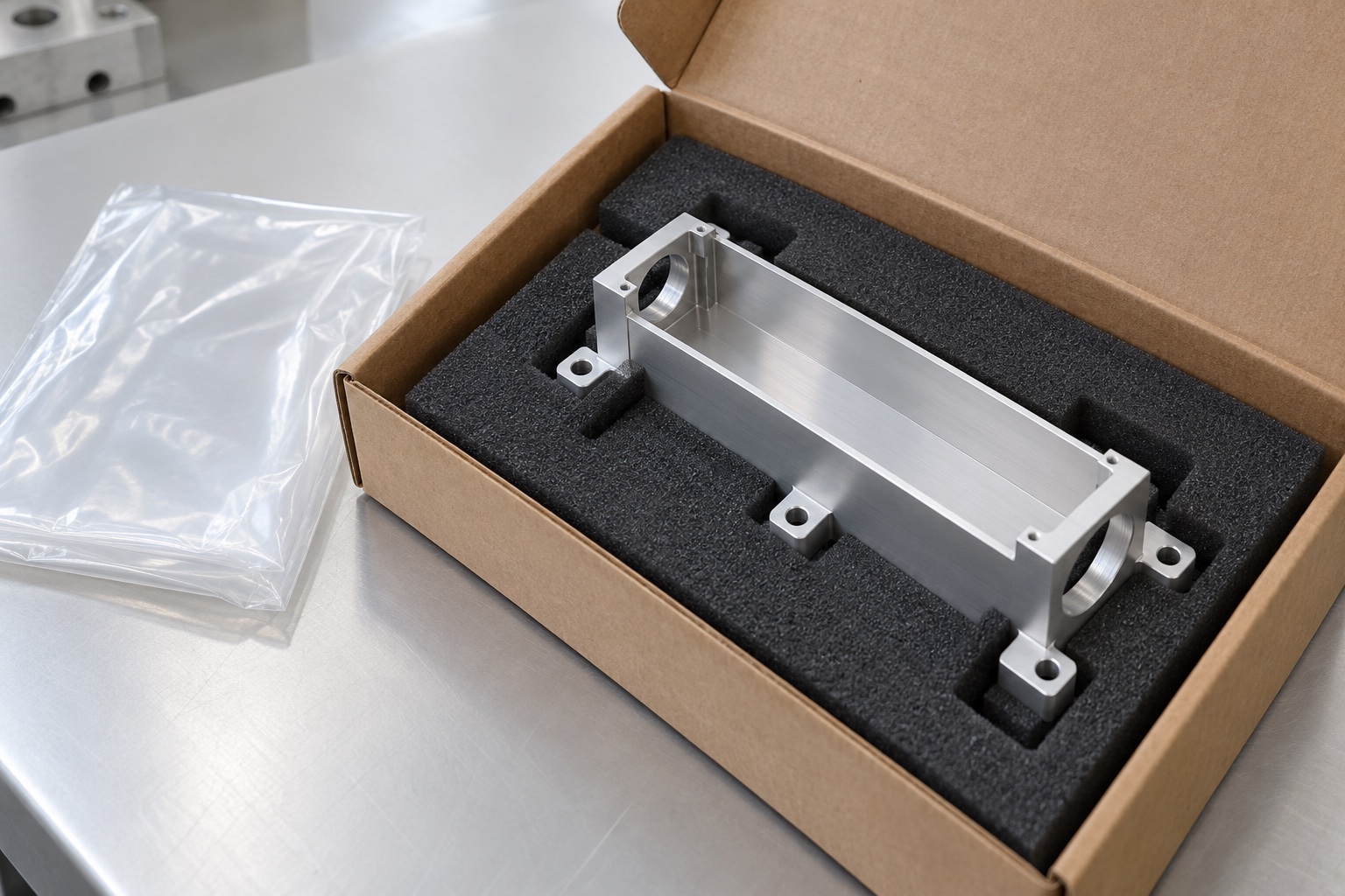
Protect apertures and the internal channel
Transport supports would locate the base and mounting regions without loading thin walls. Separate compartments would prevent impact and rubbing at apertures, cover contacts and cavity surfaces. Packaging materials would suit the agreed cleaning scope and avoid unapproved residue. Ordinary protective bags would not indicate sterile supply or quantified optical cleanliness. Any specific cleanliness criterion would have an agreed verification method. Material-lot, finish and revision records would accompany the shipment so the recipient could retain the accepted configuration and distinguish it from a prototype, trial sample or earlier internal revision.
Keep repeat orders tied to the approved design
The repeat-order package would preserve the drawing revision, material condition, aperture and cover documents, surface process, inspection method and packaging scope. Authorized prototype changes would be incorporated explicitly. The equipment owner would review changed optics, coatings or installation conditions before reusing earlier observations. This representative example provides a structured purchasing framework for a diagnostic optical body: define the internal interfaces, support the changing geometry and deliver traceable evidence. It keeps optical performance, measurement accuracy and complete medical-device validation separate from unsupported claims about an individually machined aluminum component.
Manufacturer background reference: www.thorlabs.com.
FAQ
Is this a delivered and optically qualified customer project?
No. It is a representative CNC manufacturing example for a proposed body. No actual customer shipment, achieved tolerance, light-rejection result, detector accuracy, certification or complete medical-device validation is asserted, and the images are illustrative concepts.
What defines the aperture requirements?
Approved optical and mechanical interface documents define the geometry, mounting references and relevant relationships. A loose sample, isolated diameter or photograph of a beam does not provide a complete production specification or establish the final optical arrangement.
What would the first-part report demonstrate?
It would document agreed drawing characteristics, material identity, inspection methods and final-condition references. By itself it would not establish stray-light rejection, photometric accuracy, optical cleanliness or medical-device performance of the assembled diagnostic instrument.
Does the illustrated silver surface define the final finish?
No. The images illustrate geometry. Any required coating, masking, documentation and final-condition inspection must be approved separately. Color or appearance does not prove a specified optical response or compatibility with the actual operating and cleaning environment.
Can cover seating be checked before delivery?
Yes, using identified parts, a written procedure and explicitly agreed seating, access or clearance checks. The trial remains separate from optical and device-level qualification unless those activities are independently specified, authorized and documented for the complete configuration.
Which changes require review for repeat production?
Review aperture geometry, cavity transitions, cover, optics, material, final process and mounting conditions. Preserve approved revisions and evidence rather than transferring earlier assembly or optical conclusions to an altered diagnostic configuration automatically.

tanghangyun@oemach.com