
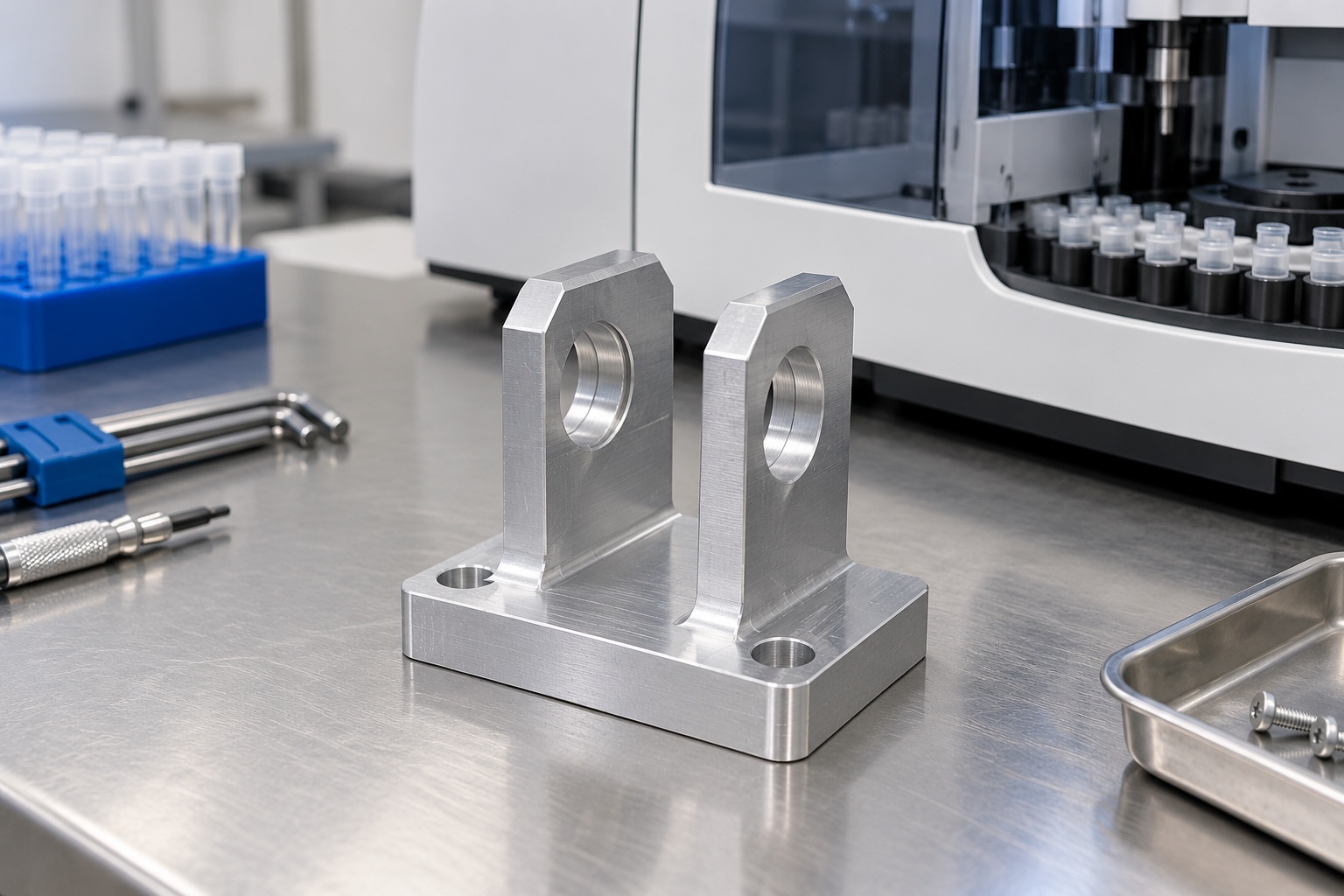
A representative proposed support fork
This example considers a proposed one-piece 6061 aluminum fork for an idler assembly inside medical diagnostic equipment. It has a mounting base, two upright cheeks and transverse axle bores. It is a representative manufacturing example, not an actual customer delivery, a load-rated bracket or a validated medical device. The pictures illustrate concepts rather than achieved dimensions or test results. Final geometry, material condition and acceptance requirements would need approved project documents. No measured tolerance, belt life, positioning accuracy, certification or safe operating speed is claimed for this proposed component.

Review the controlled interface package
The proposed order would begin with a controlled model and drawing, approved axle and pulley information, retention details and mounting references. The review would separate supporting contacts from clearances and appearance surfaces. A detached sample shaft would not define the complete assembly. Missing information about cheek spacing, tool access or axial location would be returned for written clarification before costing and routing were finalized. The purchased scope would distinguish dimensional manufacture, an optional assembly trial and any separate load or equipment-level evaluation assigned to the responsible design program.
Preserve the specified aluminum identity
Raw stock would be purchased as the approved 6061 material with its specified condition and documentation. Lot identity would remain associated with cut blanks, machined forks and finished deliveries. Similar appearance would not establish material equivalence. Stock form and machining allowance would be reviewed against the open geometry and the planned route. Any substitution intended to improve cost or availability would need authorization before use. The material designation would remain a design input rather than a general guarantee of cleaning compatibility, fatigue performance or suitability for every medical equipment environment.
Establish stable base references
Initial machining would establish the base and references needed for later operations. Workholding would support the blank without relying on distortion to achieve an apparent location. Chips at fixture contacts would be controlled before each transfer. The supplier would consider how the workpiece changes as the central opening is produced and the cheeks become less supported. Intermediate checks could confirm the route but would not replace final acceptance. The intended output would be repeatable free geometry within the drawing-defined condition, not one correct-looking part maintained by excessive fixture force.
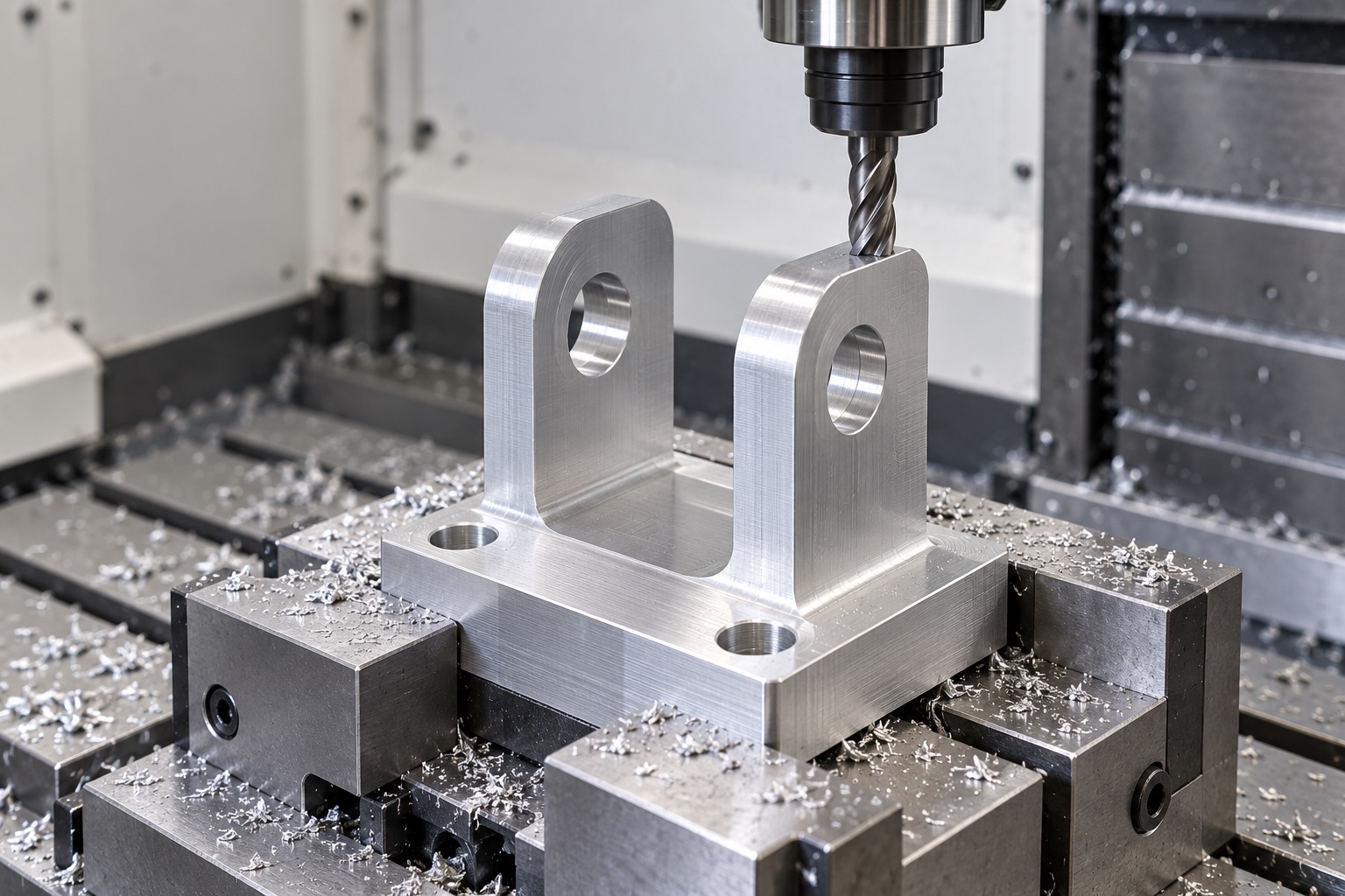
Machine the opening and cheek spacing
The central opening would be machined to the approved relationship between the cheeks and the mounting base. Internal corner radii and tool approach would be reviewed before production so they did not unexpectedly obstruct a pulley, spacer or installation tool. Any proposed relief would require approval. The supplier would not widen the fork informally to fit an unidentified sample. The controlled drawing would remain the acceptance basis for the first component and later orders, and a changed pulley width would trigger interface review rather than an undocumented adjustment at the machine.
Produce axle features from functional references
The axle bores would be related to the approved mounting references and each other as defined by the drawing. The selected manufacturing method would depend on actual geometry, access and requirements rather than an assumed universal drilling or boring sequence. The supplier would preserve these relationships through any additional setups. A shaft passing through both cheeks would not automatically verify every bore requirement. The inspection route would separately address the specified dimensions and geometry, with the identity and acceptance meaning of any approved trial axle recorded in the first-part package.
Complete mounting features and assembly access
Base mounting holes and any specified recesses would follow the approved fastener arrangement. The review would include screw-head seating, tightening-tool access and axle insertion after installation. Model and drawing discrepancies would be resolved before production decisions. Burrs at underside exits and internal transitions would be examined deliberately rather than checking only the visible upper faces. Any accepted revision would enter the controlled geometry and inspection documents. It would not remain hidden in a shop sample or an instruction to the assembly operator to force the parts together.
Apply the agreed final condition
If anodizing or another process were specified, masking, documentation and final-condition inspection would be agreed beforehand. A bore or mounting contact would not receive an unapproved finish merely to create uniform appearance. Edge finishing would preserve the geometry and not conceal a spacing problem through uncontrolled rounding. Markings would stay in approved areas. The example makes no claim that appearance proves cleanliness, corrosion resistance or chemical compatibility. Any changed treatment would be reviewed against the accepted configuration before it entered production, packaging or the repeat-order baseline.
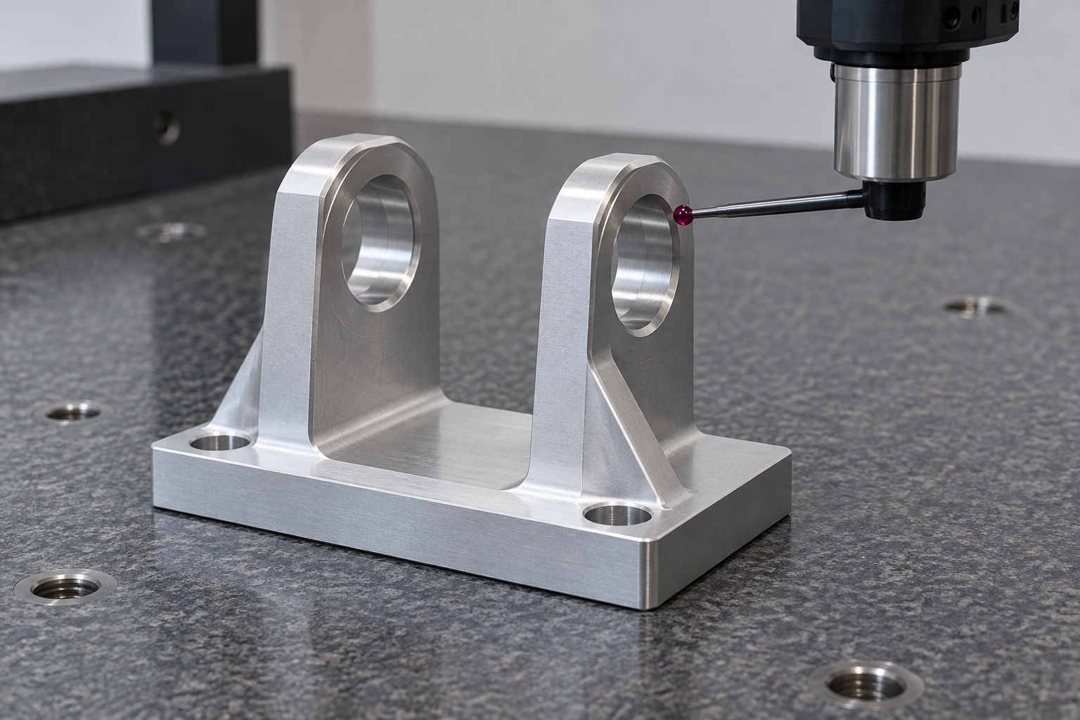
Prepare traceable first-part evidence
The report would identify the drawing revision, material lot and numbered requirements. It would cover the specified mounting geometry, cheek spacing and axle relationships using appropriate methods, recording support conditions and any defined gauges. No numerical results are supplied because this representative example has no manufactured sample or inspection record. Material and dimensional evidence would support acceptance only within the purchased component scope. It would not establish belt tracking, bearing life, load capacity or whole-analyzer performance without the responsible program's separate evaluation of the assembled equipment configuration.
Agree a limited assembly demonstration
An optional trial could check axle insertion, pulley clearance and access using approved identified hardware. The written procedure would record the fork revision, axle, spacers, pulley and mounting arrangement. A hand-rotation demonstration would not be described as life or load qualification. Unexpected contact would be documented before changing the fork or other parts. A modified sample would not become the production standard without authorization and corresponding acceptance documents. Results from one arrangement would not automatically apply to a different belt layout, pulley width, support structure or retention method.
Package without loading the cheeks
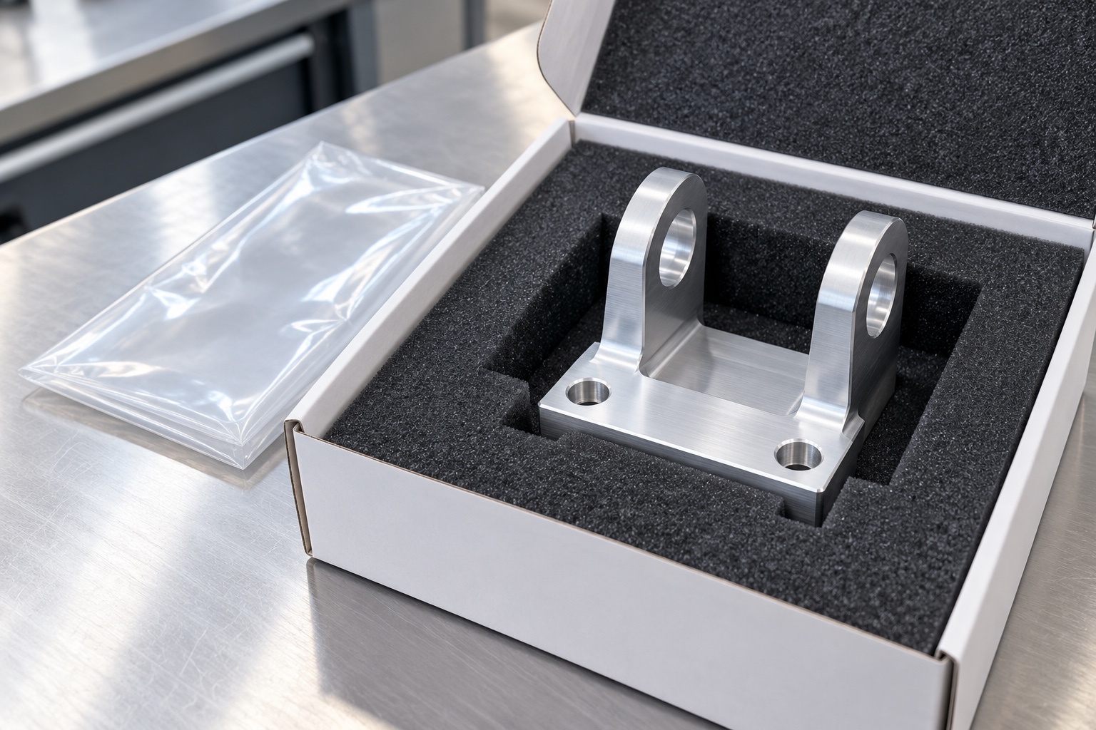
Transport supports would locate the base and separate the component from neighboring metal parts. The cheeks and axle-bore edges would be protected from impact without squeezing the fork into a forced shape. Any supplied axle or spacer would retain its approved production identity or explicit trial status. Cleaning would follow the purchased scope; an ordinary bag would not imply sterile delivery or quantified cleanliness. Revision, lot and material evidence would accompany the shipment so the recipient could preserve the accepted configuration and avoid substituting an undocumented visually similar part.
Retain the approved production baseline
Repeat manufacture would preserve the drawing revision, material condition, axle and pulley documents, final process, inspection method and packaging scope. Authorized prototype changes would be incorporated explicitly. The equipment owner would review altered hardware, belt routing or installation conditions before reusing earlier observations. This representative example provides a practical purchasing framework for a medical analyzer support fork: define the interfaces, support the changing geometry and deliver traceable evidence. It keeps drive reliability, load capacity and complete medical-device validation separate from claims that a component drawing and dimensional report cannot establish on their own.
Manufacturer background reference: www.gates.com.
FAQ
Is this a delivered and load-qualified customer project?
No. It is a representative CNC manufacturing example for a proposed fork. No actual customer shipment, achieved tolerance, load rating, drive life, certification or complete medical-device validation is asserted, and the illustrations are not inspection evidence.
What defines the spacing between the cheeks?
The approved component drawing and mating-interface documents define the spacing and its references. Pulley width, spacers, installation sequence and required clearance must be reviewed together rather than copied from an unapproved loose sample.
What would the first-part report show?
It would document agreed drawing characteristics, material identity, references and inspection conditions. A shaft fit check would have only its explicitly assigned meaning and would not establish all geometry, belt tracking or operating-load performance.
May a fork be adjusted by hand for a prototype?
Only within an approved process and drawing limits. A design change requires authorization, controlled documents and corresponding inspection before it becomes a repeat-production configuration instead of an undocumented one-off fitting operation.
Can the supplier include a pulley assembly trial?
Yes, with identified hardware, a written procedure and explicit insertion, access or clearance checks. It remains separate from motion performance, life, load and safety evaluation unless those activities are independently defined, authorized and documented.
Which changes need review before repeating production?
Review axle and pulley geometry, spacers, retention, belt layout, mounting support, material and final process. Preserve accepted revisions and evidence instead of silently carrying earlier assembly conclusions into an altered equipment configuration.

tanghangyun@oemach.com