
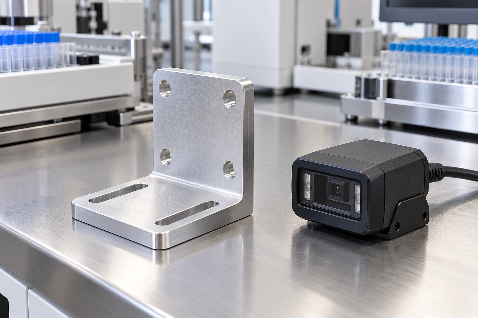
A proposed bracket, not a delivered reader system
This representative example considers an integral 6061 aluminum right-angle bracket with base adjustment slots and a reader mounting-hole pattern. It illustrates a possible manufacturing workflow for diagnostic equipment. It is not an actual customer delivery, a certified accessory or a validated identification system. The pictures are engineering illustrations rather than inspection records. The final order would require an approved drawing, selected material condition and the correct mating reader information. No particular commercial reader compatibility, reading rate, angular stability or achieved tolerance is claimed without a documented project and supporting evidence.

Review the approved configuration package
The supplier would request the reader's approved mechanical configuration, mounting hardware and connector information together with the custom bracket model and drawing. The review would identify the mounting face, adjustment direction and required access. Reference dimensions from a catalog would not silently become acceptance limits for the bracket. A discrepancy between model and drawing would be resolved before the cost estimate and machining route were finalized. The scope would distinguish component manufacture, optional assembly checking and the equipment program's separate barcode-reading evaluation, avoiding an implicit promise about complete system performance.
Maintain material and blank identity
The raw material purchase would specify 6061 together with its required condition and documentation. Identification would remain associated with the production lot after blanks were cut. A visually similar aluminum piece would not be an automatic substitute. The proposed bracket's suitability would depend on the approved design and equipment environment, not simply the familiarity of the alloy. The supplier would review the blank form and machining allowance against the integral right-angle geometry. Any change intended to reduce cost or improve tool access would need authorization before it altered the controlled component configuration.
Plan stable support for the upright
The manufacturing route would preserve adequate support while establishing the base and upright surfaces. Workholding would avoid bending the upright to meet a setup reference. The supplier would control chips beneath contact locations and check access for the relevant tools. Intermediate measurements could confirm the route before critical finishing operations, but would not replace final inspection. If substantial material removal changed the released geometry, the route would be reviewed rather than compensating through undocumented clamping force. The intended result would be a repeatable process, not a single bracket that appears correct only while restrained.
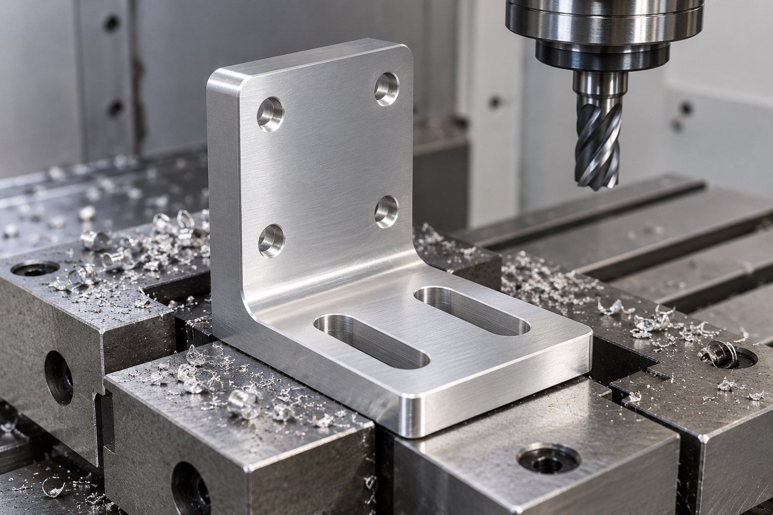
Transfer the functional references
The base and selected mounting references would define how subsequent setups locate the part. The route would preserve the required relationship between the reader face and the base rather than treating each face as an unrelated surface. Setup transfers would be documented where they affect the drawing requirements. If several brackets shared a fixture, each position would have suitable support and tool clearance. The supplier would distinguish fixture verification from component acceptance: locating a blank correctly in a fixture would not prove that every finished mounting surface and hole pattern met the approved drawing.
Machine the adjustment slots
The slot operation would follow the approved width, length and end geometry, with corner conditions reviewed for tool access. The supplier would check entry and exit edges for burrs and preserve any specified fastener contact surfaces. An informal slot extension to accommodate a sample installation would not be accepted as a hidden process adjustment. If the equipment team needed more travel, that would become a controlled design change. Washer support and screw-head clearance would remain assembly requirements defined by the designer rather than assumptions made from the appearance of the slotted base.
Complete the reader mounting features
The reader hole pattern would be produced relative to the controlled references. Any screw threads, counterbores or countersinks would follow the approved drawing and hardware information. The review would include installation-tool access and nearby internal radii. A nominally correct hole position would not resolve a reader-body interference at the bracket corner. Open issues would be returned to the equipment owner before production. The process would not alter fastener engagement or mounting-face geometry based on an unapproved reader sample, and any authorized revision would be reflected in the final inspection plan.
Finish without changing the interface
Edge finishing would remove unwanted burrs while preserving the approved reference surfaces and slot geometry. If anodizing were specified, masking and final-state measurements would be agreed before the treatment step. The example does not assign a coating thickness or claim universal cleaning compatibility. Appearance requirements could be reported separately from functional acceptance. Material, treatment and lot records would remain linked to the order. A different finishing source would require appropriate review of the accepted configuration instead of being treated as a harmless cosmetic change with no possible interface consequences.
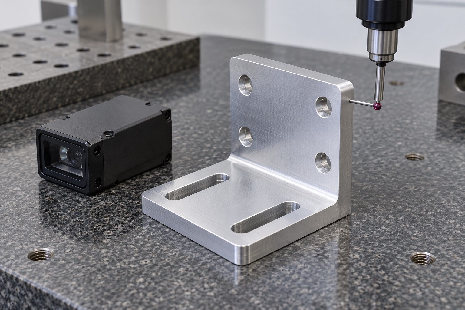
Create the first-part inspection evidence
The proposed first-part report would identify the drawing revision and numbered features, including the reader-face relationship, base references and specified mounting geometry. It would state the support and measurement condition. No numerical result is presented because there is no supplied physical specimen or measurement report for this example. The evidence package would document the purchased dimensional scope, not a reading-performance claim. If the drawing required an installed-condition check, its mounting arrangement would be defined and recorded separately rather than substituted for a required free-condition acceptance measurement.
Define the optional mating trial
An optional trial could use an identified reader, connector and hardware set to check mounting access, adjustment and agreed cable clearance. The procedure would record bracket revision and installation position. It would not demonstrate diagnostic suitability, identification accuracy or reliable reading under all operating conditions. Those belong to the responsible equipment program's evaluation. If interference appeared, the team would document the location and seek approval before changing the bracket. Hand fitting a single demonstration unit would not become a valid repeat-production standard without updated drawings and corresponding inspection requirements.
Package the mounting surfaces safely
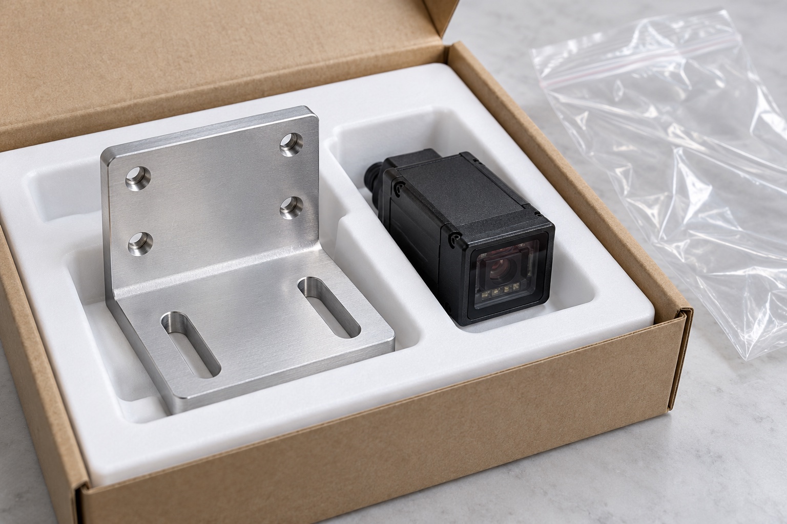
Protective packaging would support the bracket without loading the upright and would separate parts so that slots and reference faces did not rub. The scope would identify any cleaning requirement and how it would be verified. Ordinary component protection would not imply sterile packaging or cleanroom qualification. Identification and revision information would travel with the lot rather than being applied to a functional contact area without permission. If a reader were included solely as an agreed assembly sample, it would be documented separately from the machined bracket and would not be represented as a newly qualified equipment system.
Preserve the approved production baseline
Before repeat manufacture, the order would confirm the approved drawing, material condition, finish, inspection plan and any authorized prototype changes. The equipment owner would review changes to reader configuration, connector access or mounting support. The supplier could then estimate production against a defined mechanical interface and evidence package. This representative example shows how CNC machining can support diagnostic equipment integration without inventing a customer outcome. Its value is the controlled sequence from interface review to documented component acceptance, with barcode-reading and device-level validation remaining separate responsibilities that require their own evidence.
Manufacturer background reference: docs.cognex.com.
FAQ
Is this an actual delivered customer project?
No. It is a representative manufacturing example. No customer, shipment, achieved tolerance, certification or validated barcode-reading result is asserted, and the illustrations are not production inspection evidence.
What defines the mounting-hole pattern?
The approved custom drawing and selected reader configuration define the interface. A catalog illustration or unapproved sample should not be treated as a complete production specification or proof of compatibility.
Why inspect after releasing workholding?
The upright can be affected by clamping and material removal. Inspection in the drawing-defined condition helps reveal geometry hidden by the fixture; a separately specified installed-condition check may also be required.
Can slot length be changed to make a prototype fit?
Only through an approved design change. The revised geometry, hardware contact and inspection requirements must be recorded before it becomes the repeat-production configuration rather than an undocumented hand-fitted sample.
Would a mating trial prove identification accuracy?
No. It would cover only the agreed mechanical checks using identified components. Reading evaluation needs defined codes, operating conditions and acceptance criteria established by the responsible equipment program.
Which records support repeat manufacture?
Retain the approved revision, material identity, finish requirements, reference scheme, inspection plan and authorized changes. Review a changed reader, connector or mounting support before repeating the prior bracket order.

tanghangyun@oemach.com