
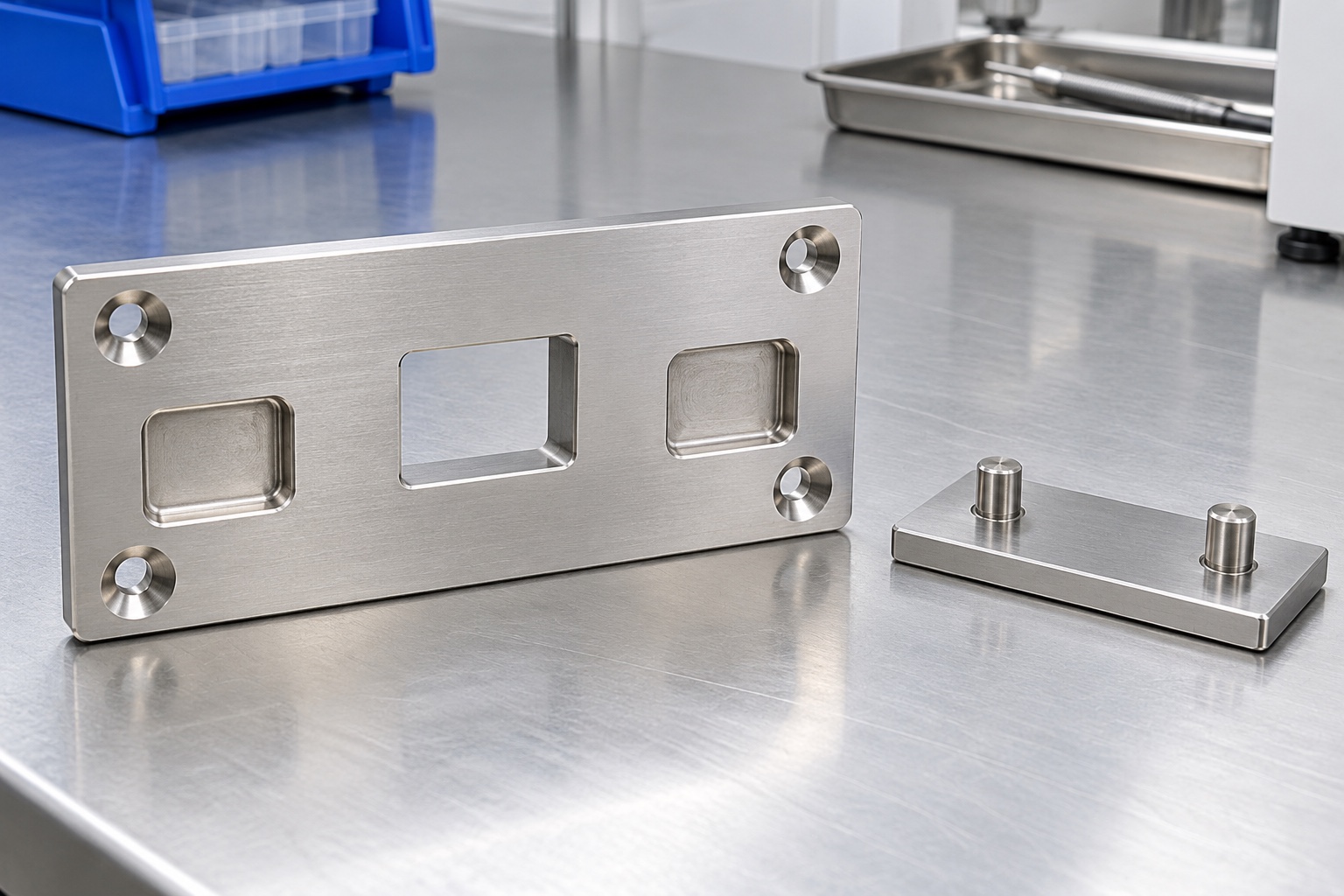
A representative receiver concept
This example considers a proposed 316L stainless steel receiver plate with locating recesses, a latch clearance window and a mounting-hole pattern for an equipment-side docking interface. It is a representative manufacturing plan, not a report of a delivered customer order or a tested medical docking system. No load rating, endurance result, certification or device approval is claimed. Illustrations show possible manufacturing stages rather than a controlled production record. The final geometry and scope would depend on the equipment owner's approved drawing, mating components and installation requirements before a production order could proceed.

Collect the complete mating arrangement
The review package would include the receiver drawing, three-dimensional model, mating component information and approved retention hardware. It would identify the mounting face, insertion direction and expected service access. The supplier would ask which features establish position and which provide retention or clearance. A photograph or isolated plate sample would not define those relationships sufficiently. Open questions about the motion envelope, corner clearance or fastener access would be returned for approval. The resulting cost estimate would state what is included in machining, inspection and any separately agreed assembly trial.
Retain the specified stainless material
The raw material order would identify 316L, the required condition and documentation. Material identification would be preserved when blanks were cut and throughout machining. A visually similar stainless plate would not be substituted without approval. The material selection in this example is a design input, not proof of corrosion resistance in every cleaning environment or of a particular safe load. The equipment team would remain responsible for application suitability. The supplier's role would be to maintain the approved material identity and produce the specified component with the agreed evidence package.
Establish stable mounting references
The manufacturing route would begin by establishing the reference surfaces needed to relate the mounting plane, locating recesses and latch window. Workholding would support the blank without forcing it into a misleading shape. Chips under setup contacts would be controlled because they can alter reference transfer. Intermediate checks would help confirm the route before critical finishing operations. If a requirement applied to the free condition, it would be measured after releasing the clamps. A defined installed-condition check could be added separately, but it would not silently replace the drawing's free-condition acceptance requirements.

Machine the locating recesses
The locating recesses would be machined in relation to the approved reference scheme, with tool access and internal corner geometry reviewed beforehand. Their function would depend on the mating features, so the route would not treat them as decorative pockets. Finishing would preserve the required contact surfaces and avoid uncontrolled blending at transitions. If a tool limitation required a different inside radius, that change would be approved before production. The inspection plan would then check the relevant size and geometric relationships instead of accepting the recesses solely because the mating sample appeared to enter them.
Open and finish the latch window
The latch window operation would preserve local support while producing the approved opening and corner geometry. Clearance would be reviewed for the hardware's movement rather than only for its final resting position. The proposed route would keep burrs and loose chips away from hidden edges and the underside. A machining supplier would not enlarge the window informally to make an unspecified latch fit. Any interference would become an engineering clarification, with the approved revision updated where necessary. The custom window would not inherit performance claims from a purchased latch catalog.
Complete the mounting-hole pattern
Mounting holes, counterbores or countersinks would be produced to the controlled drawing and related to the functional references. The review would include approved screw-head geometry and access for the intended installation tool. An apparently minor change to a countersink can affect seating or available clearance, so it would not be treated as a cosmetic adjustment. Hole exits would be examined for burrs, especially near surfaces that mate with the support structure. The supplier would document any unresolved difference between the model and drawing before making a production decision.
Apply the specified final surface process
The example could include a specified final treatment if required by the equipment design, with process documentation and final-state inspection agreed in advance. It does not prescribe a universal passivation route or assume that a bright finish proves cleanliness. Edge treatment would preserve locating geometry while removing unwanted burrs at the window and mounting features. Any marking would be placed only in approved areas. A changed treatment source or revised cleaning process would be reviewed against the accepted component configuration instead of being absorbed as an unrecorded supplier preference.
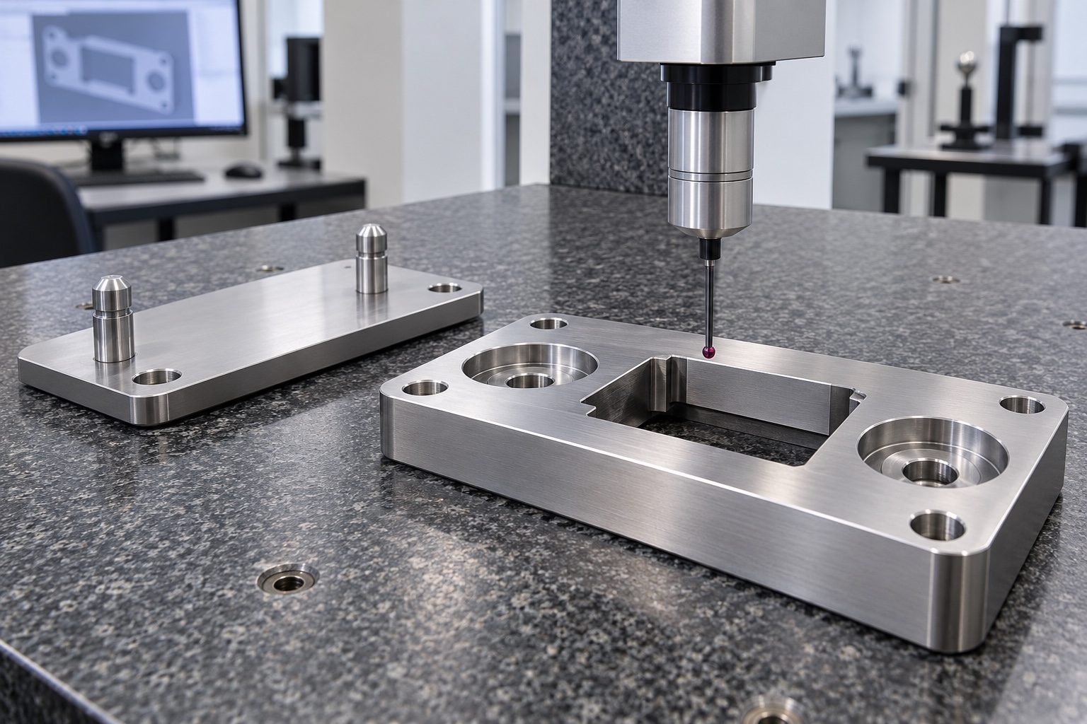
Produce a drawing-linked inspection report
The report would identify the drawing revision, material lot and numbered features. It would cover the relevant mounting-plane relationships, locating recess geometry and latch-window clearance. The measurement method would be selected for the actual requirement, with support and reference conditions recorded. No numerical inspection outcome is presented because this example has no supplied production specimen or measurement record. A dimensional report could support component acceptance within the agreed purchase scope, but it would not establish the docking system's holding capacity, fatigue behavior or medical-device safety status.
Define an optional assembly demonstration
A separately agreed demonstration could use identified mating hardware to check insertion, seating, latch clearance and removal under a written procedure. The record would state the receiver revision and mounting arrangement. It would not be described as a load or endurance qualification unless those tests were explicitly defined and performed by the responsible program. If contact occurred at an unintended location, the team would document it before changing the receiver or mating component. Hand fitting one sample would not replace the controlled drawing or become evidence that all future assemblies will behave identically.
Protect the receiving geometry
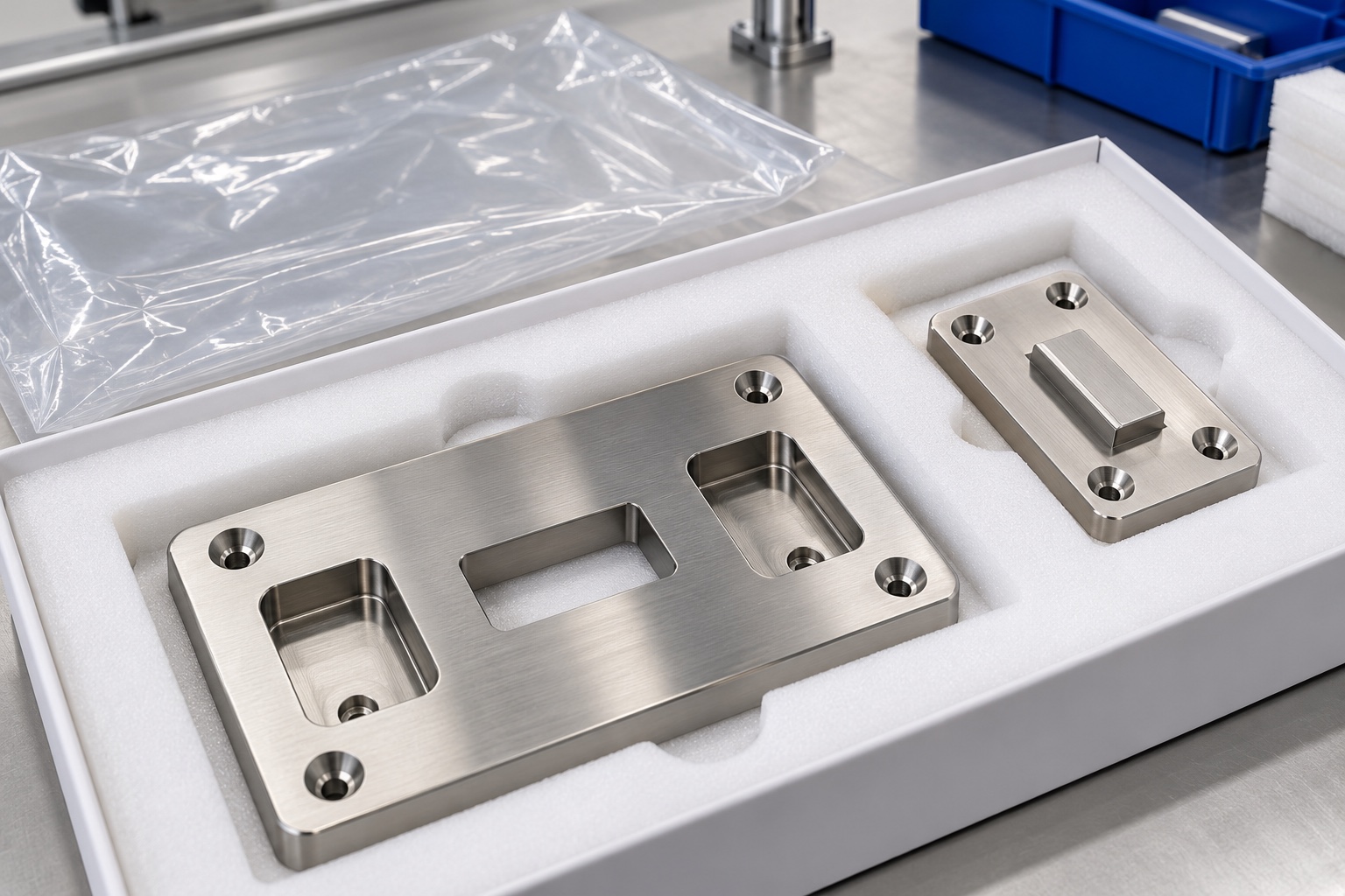
The packaging plan would separate the receiver and mating parts in protective supports, preventing metal-to-metal impact at locating surfaces. Recesses and latch windows would be checked for trapped debris before packing according to the agreed scope. Ordinary transport protection would not be represented as sterile packaging. Identification, material evidence and inspection documents would remain connected to the lot. The recipient would need a removal method that does not scrape functional surfaces against packaging hardware. If the order specified a cleanliness acceptance level, the agreed verification method would remain distinct from the visual appearance of the package.
Approve the configuration for repeat manufacture
The repeat-order record would preserve the drawing revision, mating-interface documents, hardware configuration, material condition, surface process and inspection requirements. Any prototype changes would require written approval before being incorporated into production. A later change to the support structure, latch or installation method would trigger review of the interface rather than an automatic repeat of the earlier part description. This representative example offers a practical purchasing framework for CNC medical equipment components: define geometry and evidence clearly, preserve configuration control and avoid claiming a completed validation program where none has been documented.
Manufacturer background reference: southco.com.
FAQ
Is this a delivered and load-tested docking system?
No. It is a representative manufacturing example for a proposed receiver plate. No actual customer delivery, measured load capacity, endurance result, certification or medical-device validation is asserted.
Which documents define the receiver interface?
The approved drawing and model should be accompanied by mating geometry, retention hardware and installation information. The review must establish positioning, retention and movement clearances rather than relying on appearance alone.
Can an internal corner radius be changed by the machinist?
Not without approval when it affects the controlled geometry. Tool-access limitations should be resolved during manufacturing review, and any accepted change must be reflected in the drawing and inspection requirements.
What would the first-part report demonstrate?
It would document the agreed drawing features, references and inspection condition for the manufactured component. It would not, by itself, establish the holding capacity or safety of the complete docking assembly.
Can an assembly demonstration be purchased separately?
Yes, with identified mating parts, a written procedure and explicit acceptance criteria. Insertion and clearance checks remain distinct from load, endurance and equipment-level qualification unless those are separately authorized.
What must remain controlled for repeat production?
Retain the approved revision, mating hardware, material condition, final treatment and inspection plan. Review changes to installation or retention components before assuming the previous receiver configuration remains appropriate.

tanghangyun@oemach.com