
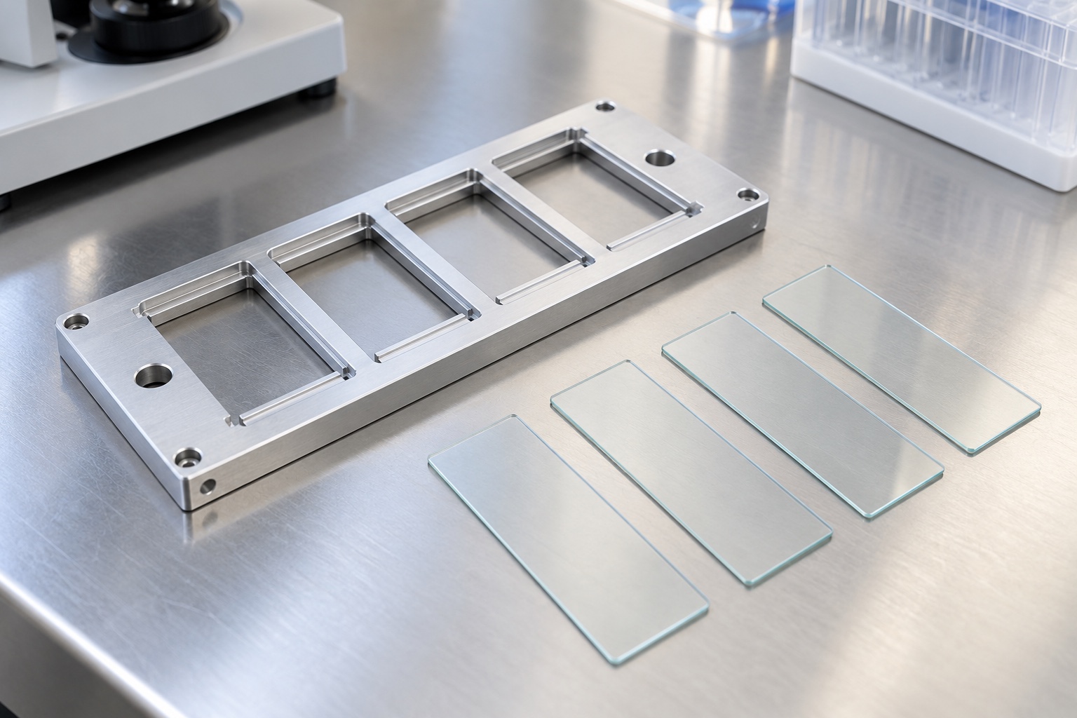
A representative equipment-side component
This manufacturing example considers a proposed 6061 aluminum carrier with several rectangular viewing windows, narrow glass support ledges, locating features and mounting holes. It illustrates how a supplier could organize CNC production for laboratory imaging equipment. It is not a report of a delivered customer project, an approved scanner accessory or a validated medical device. The images are illustrative concepts, not inspection evidence. Final geometry, material condition and acceptance criteria would be established by the equipment owner's approved engineering drawing before manufacture, and no catalog scanner compatibility is assumed.

Review the interface package first
The proposed order would begin with the model, controlled drawing and the intended loading arrangement. The review would identify where each slide rests, how the carrier enters the equipment and which surfaces must remain clear. Glass thickness, labels and coverslip envelope would be included as design inputs where relevant. A sample carrier alone would not establish all requirements, especially if it had worn edges or undocumented modifications. Open questions would be returned for written clarification before a cost estimate or production route was finalized, avoiding an implicit promise to reproduce an unknown assembly condition.
Preserve material identity
The purchasing specification would identify 6061 together with the required material condition and documentation. An aluminum designation by itself does not define every property relevant to a thin frame. Raw material identity would remain linked to the production lot as blanks were cut and processed. Any substitution would require approval rather than being treated as visually equivalent. The proposed component is an equipment support part; selecting a familiar engineering alloy would not establish biological suitability, cleaning compatibility or device certification. Those decisions require the actual application requirements and supporting evidence.
Plan supported rough machining
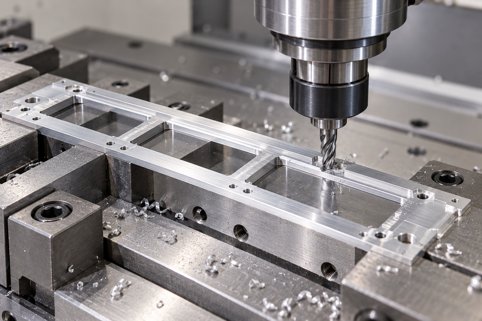
The early machining route would preserve enough material and contact area to support the frame while the viewing windows were opened. Workholding would be reviewed for access, pressure distribution and the risk of trapping chips under reference surfaces. Roughing would not be accepted as a shortcut to final geometry simply because the outer dimensions appeared correct. After substantial material removal, the carrier could be checked in its released condition before the finishing sequence was confirmed. The goal would be a controllable process, not a thin part forced into shape by a powerful fixture.
Transfer references deliberately
The mounting plane and selected locating features would define the manufacturing reference scheme agreed from the drawing. Transfers between machining setups would be documented so that the glass ledges and mounting pattern remained related to the same functional geometry. A convenient saw-cut edge would not silently become the final reference. Where multiple carriers shared a fixture, each position would need appropriate support and clearance. The route would distinguish a setup check from final acceptance, because a correct fixture position does not prove that every finished carrier meets the approved requirements.
Finish the glass support features
Window machining would leave the approved ledge width and internal corner geometry. The tool path would be reviewed around narrow support areas where a small change can remove useful contact surface. Finishing would address both the ledge and adjacent edges without creating an uncontrolled rounded transition. If separate ledges must establish a common support condition, that relationship would be measured directly. A smooth-looking pocket floor would not be enough. Any design change needed for tool access would be approved before machining instead of hidden in a shop-floor decision.
Complete holes and edge treatment
Locating holes, mounting holes and any specified screw threads would be completed in a sequence that preserved access and reference control. Hole entrances and exits would be examined for burrs that could affect mounting or glass loading. A generic instruction to break all edges would be interpreted only within the approved drawing requirements. The process would identify sensitive locating edges and thin ledges that must not be rounded indiscriminately. Loose particles would be removed with a suitable method, and cleaning would not be used to conceal a damaged functional surface.
Confirm the final surface condition
If the approved configuration required anodizing, the supplier would coordinate masking and measurement requirements before treatment. Critical fit and support features would be checked in the specified final state. Color and appearance could be documented separately from functional acceptance. The example does not assign a universal coating thickness or claim resistance to every cleaning chemical. Treatment records would remain associated with the lot, and a changed finishing source would be reviewed for its effect on the accepted configuration rather than regarded as an automatic like-for-like replacement.
Prepare a feature-linked first-part report
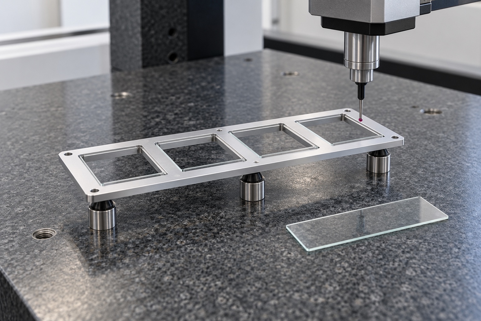
The first-part report would identify the carrier revision and map results to numbered drawing features. Measurements would include relevant mounting relationships, support geometry and window clearance rather than only the external length and width. The report would state the support condition used during measurement. If the drawing required a mounted-condition check, the method and mounting arrangement would be specified. No numerical results are claimed here because no manufactured specimen or measurement record is supplied. The example describes a proposed evidence package, not a completed acceptance report.
Agree the surrogate-glass trial
An optional assembly trial could use equipment-owner-approved blank slides and a defined mating interface. The written procedure would cover loading, seating, removal and agreed interference checks, with the component revision and sample set recorded. Such a trial would remain separate from optical calibration and scanner qualification. It would not establish that clinical samples can be safely processed or that images meet diagnostic requirements. If interference appeared, the team would document the contact location and seek an approved change before modifying ledges, windows or retaining features.
Package without loading the frame
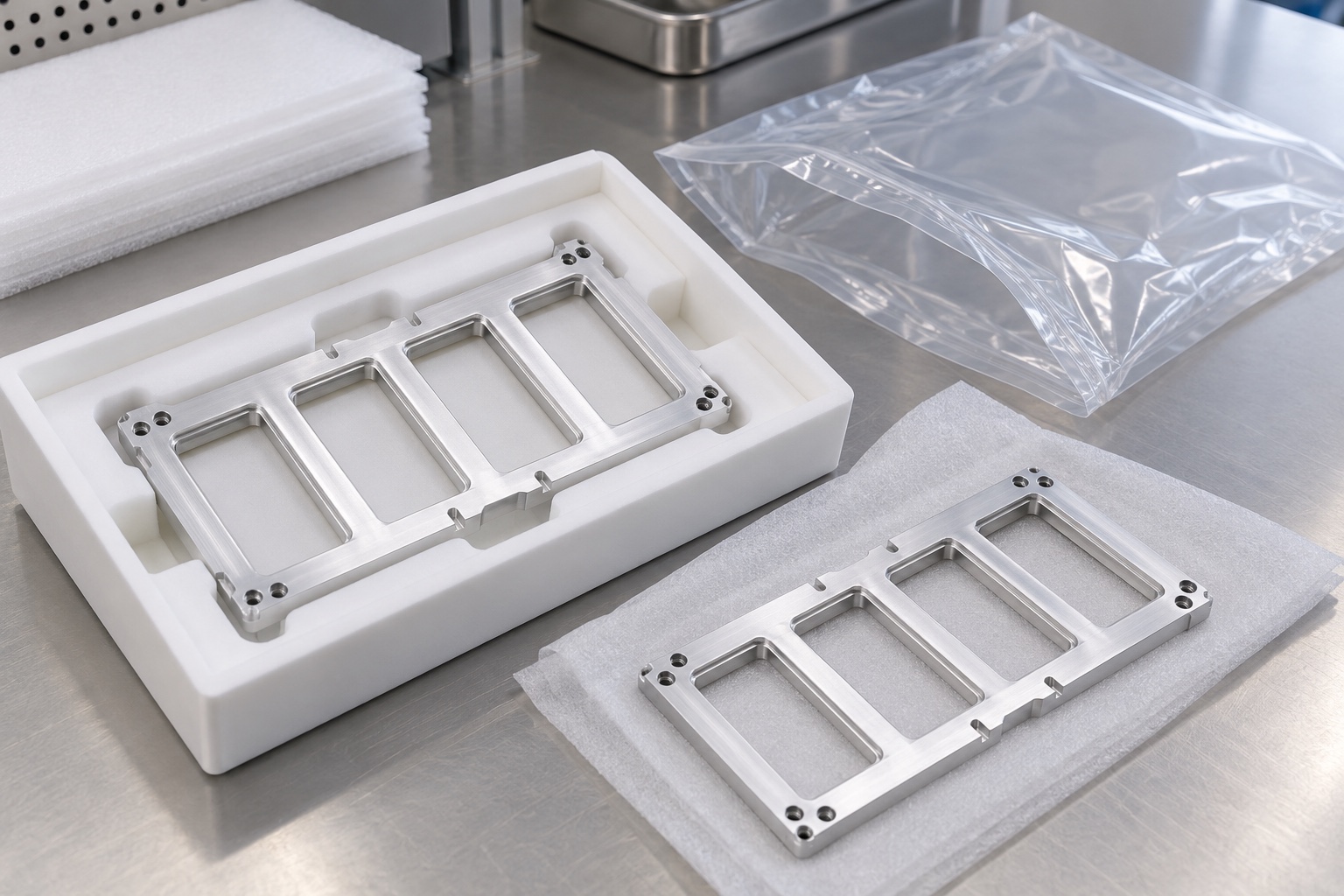
The proposed packaging would separate carriers in protective cavities or equivalent supports that avoid bending the frame and rubbing the glass ledges. Clean protective bags could reduce transport contamination when agreed, but would not imply sterility. The packaging review would consider how the recipient removes the part without catching thin features. Identification and revision information would accompany the shipment rather than being applied to a sensitive contact surface without permission. An agreed cleanliness specification, if required, would define its own verification method instead of relying on a photograph of a tidy bench.
Control the repeat production configuration
Before repeat production, the equipment owner would approve the drawing revision, inspection plan and any documented prototype changes. The supplier would retain the route, workholding approach, material specification and finishing requirements relevant to that configuration. A later change to glass envelope or scanner handling would trigger an interface review rather than being absorbed into the old order description. This representative example demonstrates a structured way to purchase a CNC carrier: define the interface, manufacture it consistently and provide agreed evidence, while leaving medical-device validation with the responsible equipment program.
Manufacturer background reference: nanozoomer.hamamatsu.com.
FAQ
Is this an actual customer delivery?
No. It is a representative manufacturing example. No customer, shipment, measured tolerance achievement, certification or validated scanner performance is claimed. The final production scope would require approved project documentation.
Why specify more than the alloy name?
The required material condition and traceability documents are part of the purchase specification. Visual similarity to another aluminum blank does not establish an approved substitution for a controlled carrier design.
What is checked after the windows are machined?
The plan would check released geometry, support ledges and their relationship to mounting references. The exact features and acceptance conditions come from the approved drawing, not a universal carrier tolerance.
Can anodizing be added after prototype approval?
Only through a reviewed change. Masking, final dimensions and contact conditions may need reassessment. A previously accepted untreated prototype does not automatically approve a treated production configuration.
Can a blank-slide loading trial be included?
Yes, as a separately defined service using approved surrogate slides and a documented procedure. It verifies only the agreed mechanical checks, not optical or diagnostic performance of the scanner.
What prevents a repeat order from changing unintentionally?
Retain the approved revision, material condition, finishing requirements, inspection method and authorized changes. Any altered glass envelope or mating interface should trigger review before the next production lot.

tanghangyun@oemach.com