
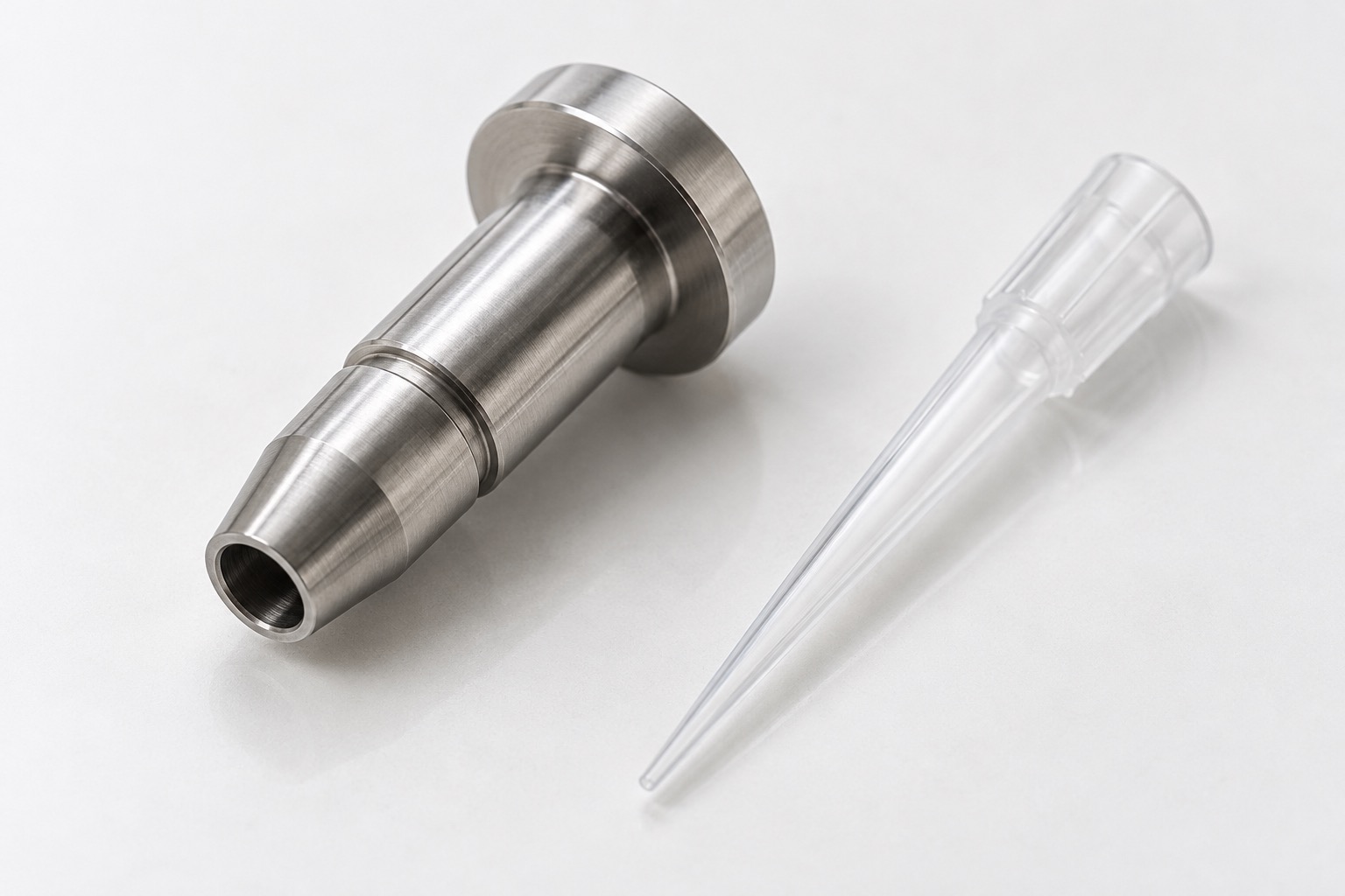
A representative diagnostic component
This case describes a representative 316L stainless steel adapter sleeve for a diagnostic liquid-handling head. The component combines a mounting flange, an accessible locating diameter, an axial passage and a short external seating profile. It is an illustrative manufacturing case, not a report of a named customer delivery or a validated device. The development team defines the consumable interface and operating requirements. The machining task is to reproduce the released geometry, control relevant edges and provide traceable evidence that the ordered part meets its drawing. The images show a generic concept rather than a proprietary replacement part.

Review the interface package
Start with a released two-dimensional drawing and a matching three-dimensional model. Identify the flange mounting face, locating axis, seat region, internal passage and any relief needed for tool or assembly access. Check which features contact the disposable tip and which merely provide clearance. Request approved mating data if fit testing is part of the order. Resolve inconsistencies between drawing, model and samples before tool selection. A sample can support a trial but should not silently replace a missing dimension. Record the revision and the disposition of any agreed clarification on the production traveler.
Keep material identity through the route
The example specifies 316L in the stock condition required by the drawing. Review the material certificate, bar dimensions and identification before cutting blanks. Retain the heat or lot reference through each batch and connect it to delivery records. Surface treatment, chemical exposure and contact classification remain device-specific requirements. If a different material or condition is proposed, obtain an engineering disposition before treating it as equivalent. Plan stock allowance for the flange, external reference and finish-bored features. Avoid mixing visually similar stainless grades in the same work-in-progress tray, where appearance cannot provide reliable material identification.
Choose a datum-first turning strategy
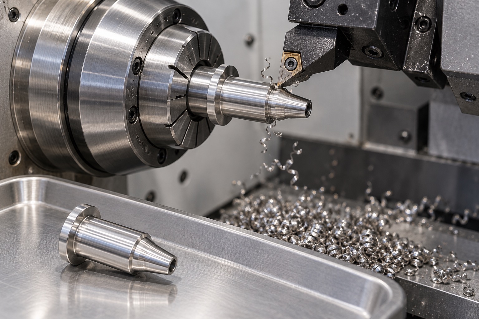
One possible route establishes the external reference and flange face, then finishes the seating profile and axial passage with minimal changes of setup. The actual order depends on stiffness, stock access and chip evacuation. Support the part with a collet or controlled jaws that do not crush a thin wall. When a second setup is necessary, define the transferred reference and allow inspection of the relationship between both operations. Track the tool and program revision used for the first article. Correcting a local diameter is not sufficient if the supporting axis has shifted.
Manage the bore and thin section
Review bore depth, entry geometry and the remaining wall between the passage and external seat. A small drill can wander; a later bore-finishing operation may be appropriate where the drawing and access justify it. The process plan should address chip evacuation and the possibility of trapped chips at an internal step. Avoid unsupported overhang that allows the sleeve to deflect. Measure the part after it is released from the fixture and has stabilized. Inspect accessible internal transitions with an appropriate method. Do not assume that a visible opening confirms the condition of the entire passage.
Finish the seat as a functional feature
The short external seat is related to the locating diameter and mounting face. Its axial location, profile and contact length are reviewed together, rather than inspecting only one diameter. Use the defined finishing process and protect the surface during transfer between operations. A shallow groove or relief must remain in the intended position and must not interrupt a contact band unexpectedly. State edge and surface acceptance clearly. If polishing is requested, agree its scope and recheck the affected geometry. Visual brightness is not a substitute for a profile or dimensional result.
Deburring and treatment planning
Bore entries and narrow reliefs receive a controlled edge process. Remove loose burrs without opening the passage beyond its requirement or rounding a locating shoulder. Review whether the selected method can reach an internal edge, and record any inspection access limitation. If passivation or another treatment is specified, use the ordered process and check compatibility with the material and final geometry. Inspect after treatment for residues, handling marks and changes relevant to fit. Neither stainless steel nor a finishing step alone demonstrates sterility. The acceptance package must describe what was actually processed and checked.
Measure the first article
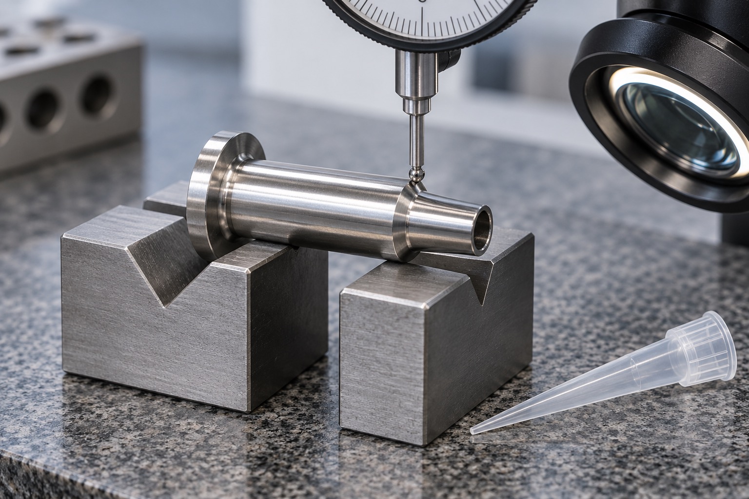
A proposed inspection layout includes material identification, flange dimensions, mounting-face condition, reference diameter, bore size, seat profile and specified geometrical relationships. Choose suitable gauges, optical equipment and contact measurement for the feature size and access. Record support conditions, measurement references and drawing-characteristic numbers. A measurement on a compressed sleeve may not describe the free part. Use the first article to review both the process and the practicality of the inspection plan. Resolve deviations before using the same settings for a repeat batch, and retain the accepted record with the program revision.
Plan any assembly trial before quoting
With approved mating components, a separate trial can assess seating, clearance, retention and release. A leakage test needs its own defined fixture, consumable, seals, medium, pressure, duration and limit. The supplier should know whether the test applies to the bare adapter, an assembled channel or another configuration. The example does not assert a universal insertion force or an achieved pipetting coefficient of variation. Those values must come from actual equipment requirements and evidence. A dimensional report and an assembly observation can complement one another without claiming that either alone validates the diagnostic instrument.
Clean and protect critical contacts
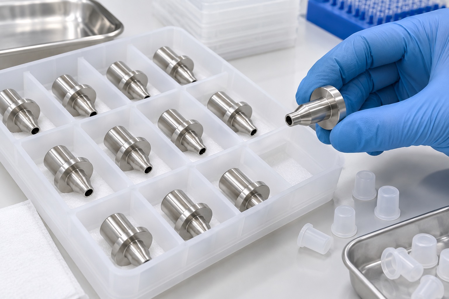
Remove chips, cutting fluid and finishing residue from the passage and outer surfaces using a compatible cleaning and drying route. Verify the agreed cleanliness condition before handling parts for packing. Use individual compartments to prevent the flange and seating profile from rubbing against adjacent metal. Caps or sleeves must not shed debris into the bore or distort its opening. Keep labels on the packaging rather than the contact band. Identify the part, revision, lot and inspection status. The protective packaging shown in this case illustrates orderly handling and damage prevention, with no implied sterile barrier or cleanroom classification.
Release a controlled repeat build
After prototype approval, freeze the drawing revision, material condition, process references, finish and inspection plan required for repeat orders. Review changes in stock source, tools, collets, deburring or treatment for their influence on the functional interface. Retain first-article disposition and any approved deviations rather than relying on a previous part photograph. Define lot sampling and any full inspection requirements in the order. If mating consumables change, the device team should determine whether an interface or trial must be reviewed. Traceability makes a later investigation specific to a lot and revision rather than a general discussion about the part family.
RFQ checklist for this adapter sleeve
A complete inquiry includes the drawing and STEP file, exact material, prototype and repeat quantities, finish, critical contact zones and requested reports. Include approved mating samples and acceptance conditions for any fit or leakage trial. State cleaning, packaging and lot-identification expectations. List features requiring measurement after treatment and clarify any internal geometry that cannot be reached directly. This lets the manufacturer quote turning, secondary operations, fixtures, inspection and documentation as defined work. No cost, lead time or tolerance capability is promised by this representative case; those commitments follow review of the actual controlled order package.
FAQ
Is this an actual customer shipment?
It is a representative manufacturing case without a named customer, shipment or medical performance claim. A real order requires its own released drawing, acceptance criteria and production evidence.
Which interfaces control the sleeve?
The mounting face, locating diameter, axial passage and tip seating profile are the main features in this example. Their exact dimensions and relationships must be defined by the device drawing.
Can the part be passivated?
Yes, when specified and compatible with the selected material and order requirements. Inspect relevant surfaces after processing and record the agreed treatment; it is not a claim of sterile delivery.
How is a small axial bore checked?
Select a method appropriate to its size, depth and access, and define what it establishes. Entry inspection alone does not verify the whole passage or a hidden internal step.
Can fit and leakage tests be included?
They can be agreed separately with approved mating parts and a defined fixture and procedure. Specify consumable, assembly state, medium, pressure, duration and acceptance conditions before quoting.
What is required for a repeat order?
The controlled drawing and model, accepted first article, material and finish, quantities, inspection plan, cleaning and packaging requirements, and any applicable change or deviation approvals.
tanghangyun@oemach.com