
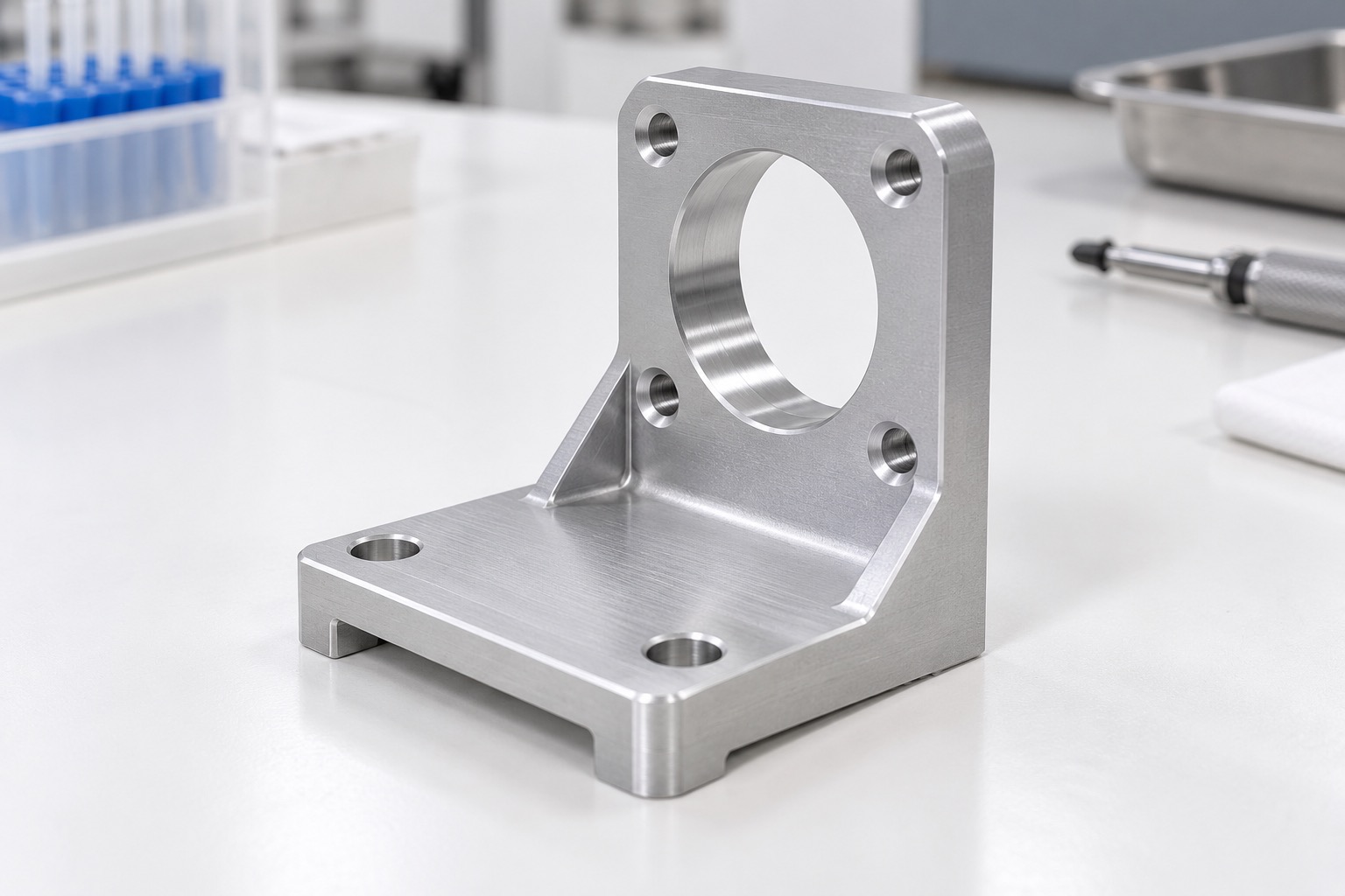
6061 Aluminum Syringe Pump Motor Mount: CNC Manufacturing Case Study
Representative component and application
This case describes a representative 6061 aluminum motor mounting bracket for the internal drive of a syringe pump. The bracket has a motor register bore, a mounting-hole pattern, frame contact pads and accessible fasteners. It is a manufacturing example, not a claim about a named customer order, certified device or measured clinical result. Its purpose is to show how a procurement team can translate an assembly interface into a controlled CNC process. The device team owns the load case, selected motor, motion arrangement and pump validation.

Drawing review and interface definition
The order package should identify the motor face, locating register, base pads and side reference. Compare the model with the controlled drawing and flag discrepancies before CAM programming. Review fastener access, tool reach, minimum wall sections and the surrounding enclosure. Clarify whether the motor is located by the register or by a separate dowel arrangement. Identify which dimensions apply after finishing. An assembly sketch can show the guide and screw references without requiring the supplier to infer the entire pump design from the shape of the bracket.
Material and traceable stock
The proposed material is 6061 in the condition specified by the drawing, for example T6 where the design requires it. Confirm the material certificate, stock form and any substitution procedure. Leave machining allowance around pads and locating faces. Record the stock lot on the production traveler so the delivered parts can be traced to the certificate. The alloy choice does not by itself establish device suitability or chemical compatibility. If the equipment cleaning process reaches this internal component, its effect on the specified surface treatment should be reviewed by the device team.
Process route and workholding
A possible route roughs the outline and main cavity, establishes the base datum, then finishes the motor face, register and mounting holes from a controlled reference. Support the upright section to avoid distortion while cutting or tightening the fixture. Use a repeatable transfer method if opposite-side access needs another setup. Do not clamp directly on a finished locating bore. The process plan records setup references, tool access and inspection stages. For a prototype, confirm fit before releasing fixtures or offsets intended for larger repeat batches.
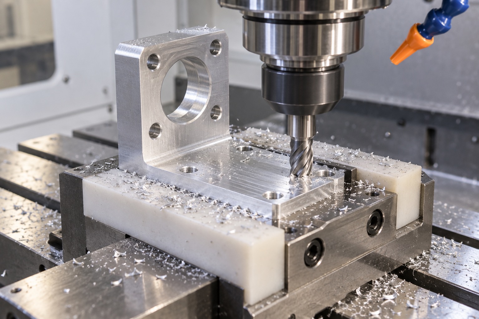
Register bore and pad relationships
The register diameter must match the approved motor interface, while its position and face orientation relate to the base and guide references. These are separate requirements. A bore can pass a size gauge while its axis or seating face is incorrectly located. Small support pads also need enough stable contact area after edge breaking. Define the intended seating surfaces and reliefs on the drawing. Inspect the free part, then use the specified assembly tightening sequence for any clamped fit check. Avoid assuming that tightening screws will correct a geometric mismatch.
Finish, threads and edge control
If anodizing is required, specify its type and relevant acceptance requirements, not only color. Agree masking for the register, datum pads, threads or electrical interfaces where needed. Keep loose burrs out of the bore and screw holes without rounding a locating shoulder beyond the drawing requirement. Verify usable thread depth and fastener clearance. Inspect after finishing for damage, residues and changes to fit. An acceptable cosmetic appearance is useful, but functional surfaces and documented mating conditions determine whether the bracket is ready for assembly.
First article and assembly evidence
An agreed first-article package can contain material identification, dimensional results for the register and hole pattern, pad flatness, face orientation and thread checks. Link results to the drawing revision and record the inspection support condition. With customer-supplied mating components, a mechanical trial can check register fit, screw access and movement clearance. Define the test before quoting and separate it from pump-level performance verification. No flow rate, tolerance capability or production yield is asserted here without actual approved data for the ordered configuration.
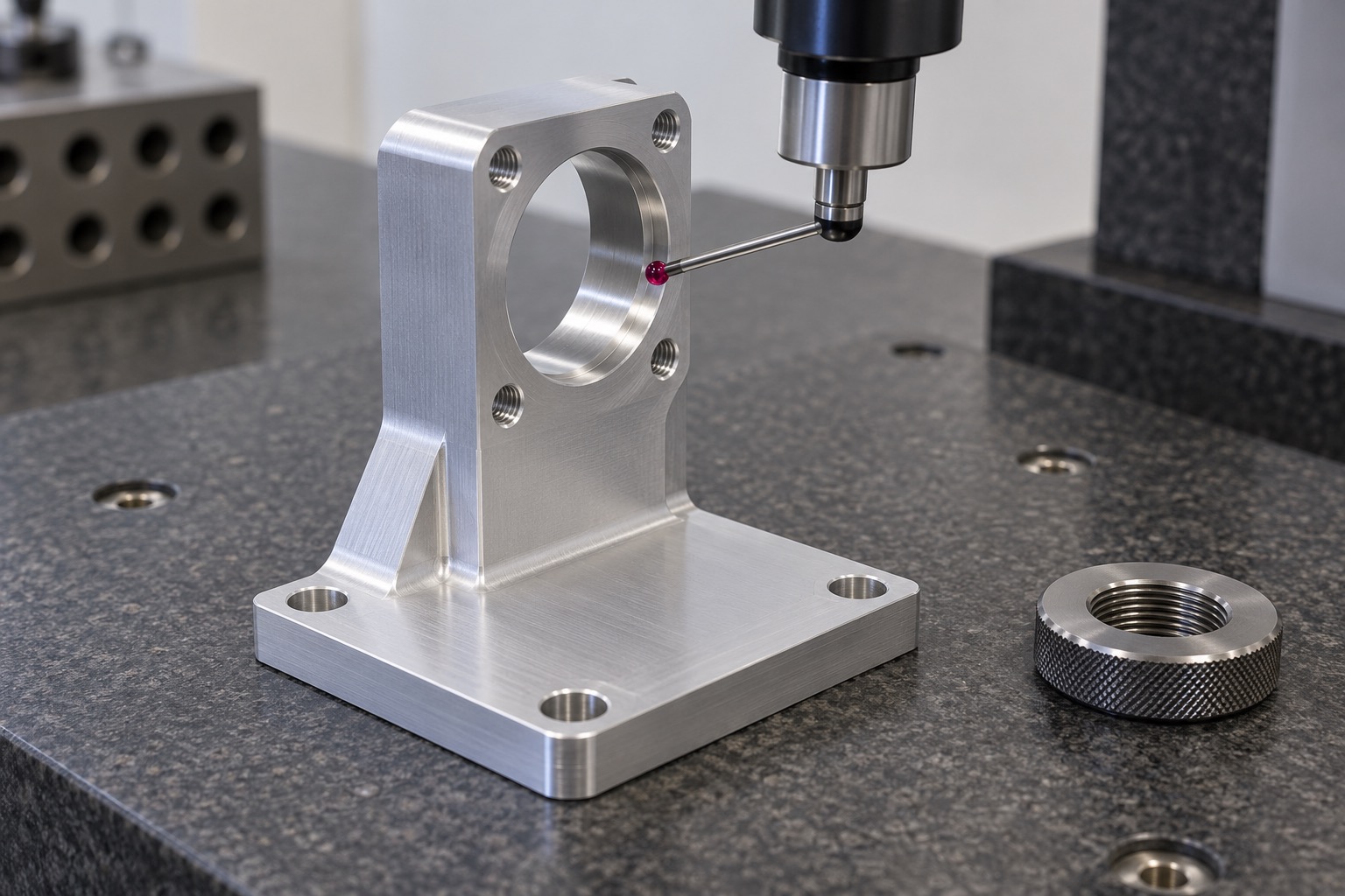
Clean handling and protective delivery
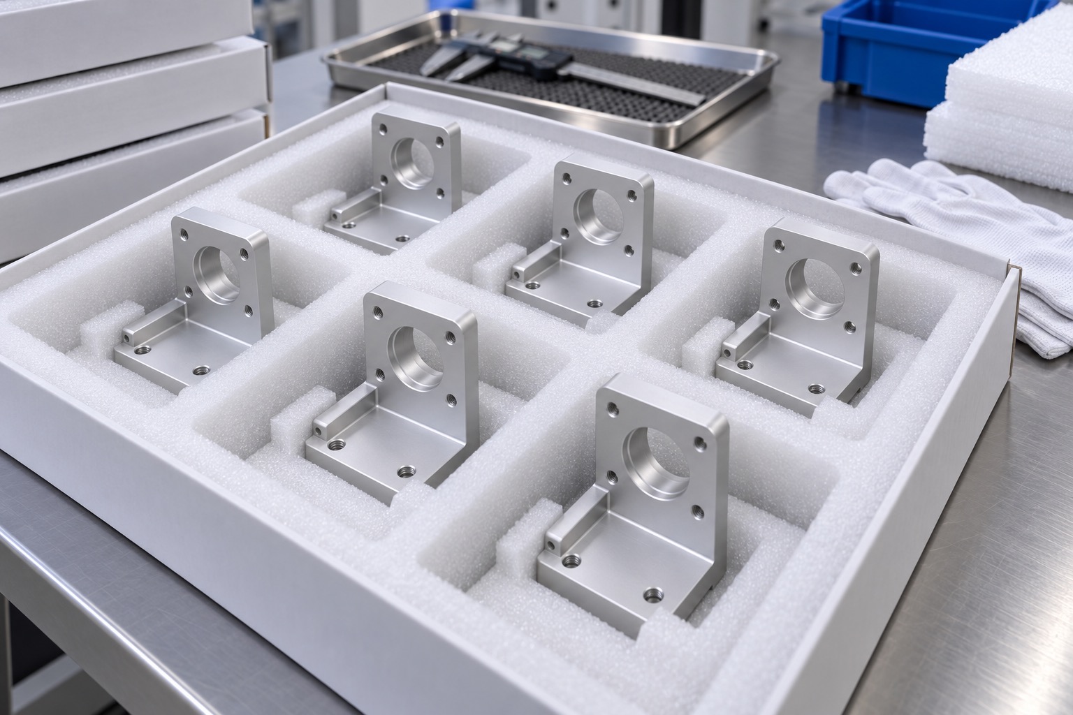
After machining and finishing, remove chips and residues from pockets, bores and threads. Use compatible cleaning and drying methods and verify the agreed cleanliness condition. Separate brackets in protective trays or individual packaging so datum pads and register surfaces do not rub together. Avoid labels or adhesive on mating surfaces. Supply part number, revision and lot identification with the agreed inspection records. The illustrative packing photographs show damage prevention and orderly handling; they do not establish a cleanroom classification or a validated sterile barrier.
From prototype to repeat orders
A repeat-order release should reference the approved drawing, material, treatment, inspection plan and accepted first article. Review changes to stock, setup, machining strategy or coating masks before reusing previous acceptance data. Confirm order quantity and forecast separately from prototype quantity. RFQs should include STEP and dimensioned PDF files, critical interfaces, required certificates, cleaning expectations and any assembly trial. This gives the buyer a clear basis for comparing machining, fixtures and inspection cost while keeping device performance decisions with the development team.
FAQ
Is this a delivered customer case?
It is a representative manufacturing case. It does not assert a named customer, shipment, device certification or measured medical performance; actual order data must be agreed separately.
Why consider 6061 aluminum?
It can provide a practical lightweight machining option for an internal support. The designer confirms condition, loads, surface treatment and compatibility with the equipment environment.
What are the principal inspection features?
The motor register, base pads, motor-face orientation, locating-hole relationships, mounting pattern and threads should be inspected according to the released drawing and datum system.
Can the bracket be anodized?
Yes, if specified. Agree the treatment and masks, then inspect functional dimensions at the defined acceptance stage. Finishing must not undermine register fit or datum contact.
What does a prototype fit check include?
It can check the supplied motor register, fastener access and clearance to the guide, screw and housing. The mating parts and acceptance procedure must be available.
What is needed for repeat production?
A controlled drawing and model, approved material and finish, first-article disposition, inspection plan, quantity and delivery requirements, plus defined cleaning and documentation expectations.
tanghangyun@oemach.com