
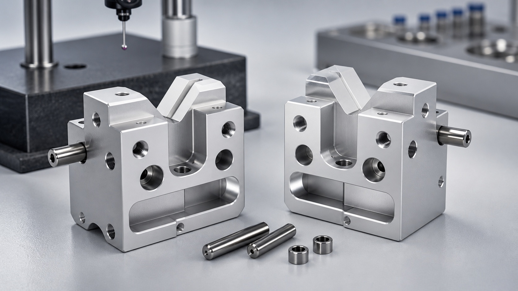
Sample Tube Gripper Jaw for Diagnostic Automation: Precision CNC Machining Case
Representative application
This case describes a representative CNC-machined gripper jaw used in a diagnostic automation module to hold or transfer sample tubes. The component includes tube-contact profiles, pivot or mounting holes, stop faces and lightweight pockets. It is a manufacturing example, not a claim about a certified analyzer. The device manufacturer owns sample handling validation, tube compatibility, contamination control and final system acceptance; the supplier controls material, machining, inspection, cleaning and delivery records.

Drawing and quote review
The released package should include a 2D drawing, 3D model, revision record, material grade, surface requirement and critical-characteristic list. Before quoting, the shop reviews tube-contact radius, jaw symmetry, pivot spacing, edge condition, burr-removal access and inspection method. Missing values such as mating tube diameter range, spring preload or allowed contact marks should be clarified before first-article planning.
Material and blank strategy
Aluminum, stainless steel or engineering polymer may be selected depending on mass, wear behavior and cleaning exposure. Certified stock is prepared with allowance for stable machining and final cleanup. Thin jaw sections are supported during machining so clamping does not alter the tube-contact profile. Lot identity remains linked to the traveler from blank preparation through shipment.
CNC process
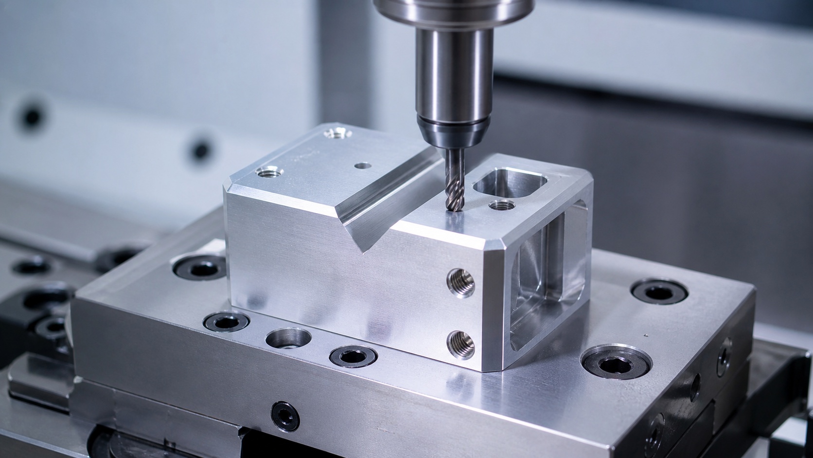
The first operations establish stable datums and rough the outer shape. Tube-contact surfaces, pivot bores, stop faces and mounting holes are finished from controlled references. Small tools are monitored because wear can alter the contact radius or leave raised burrs. After unclamping, the free-state jaw geometry is inspected so spring-back or fixture distortion is visible.
Contact edge control
The tube-contact profile must be clean enough to avoid scratching plastic tubes while preserving the designed grip geometry. Broad tumbling may round stops or change the contact area. Targeted deburring, magnified inspection and controlled edge breaks are used for functional edges, screw holes and handling surfaces. Any surface texture requirement should be linked to the drawing and test method.
Inspection package
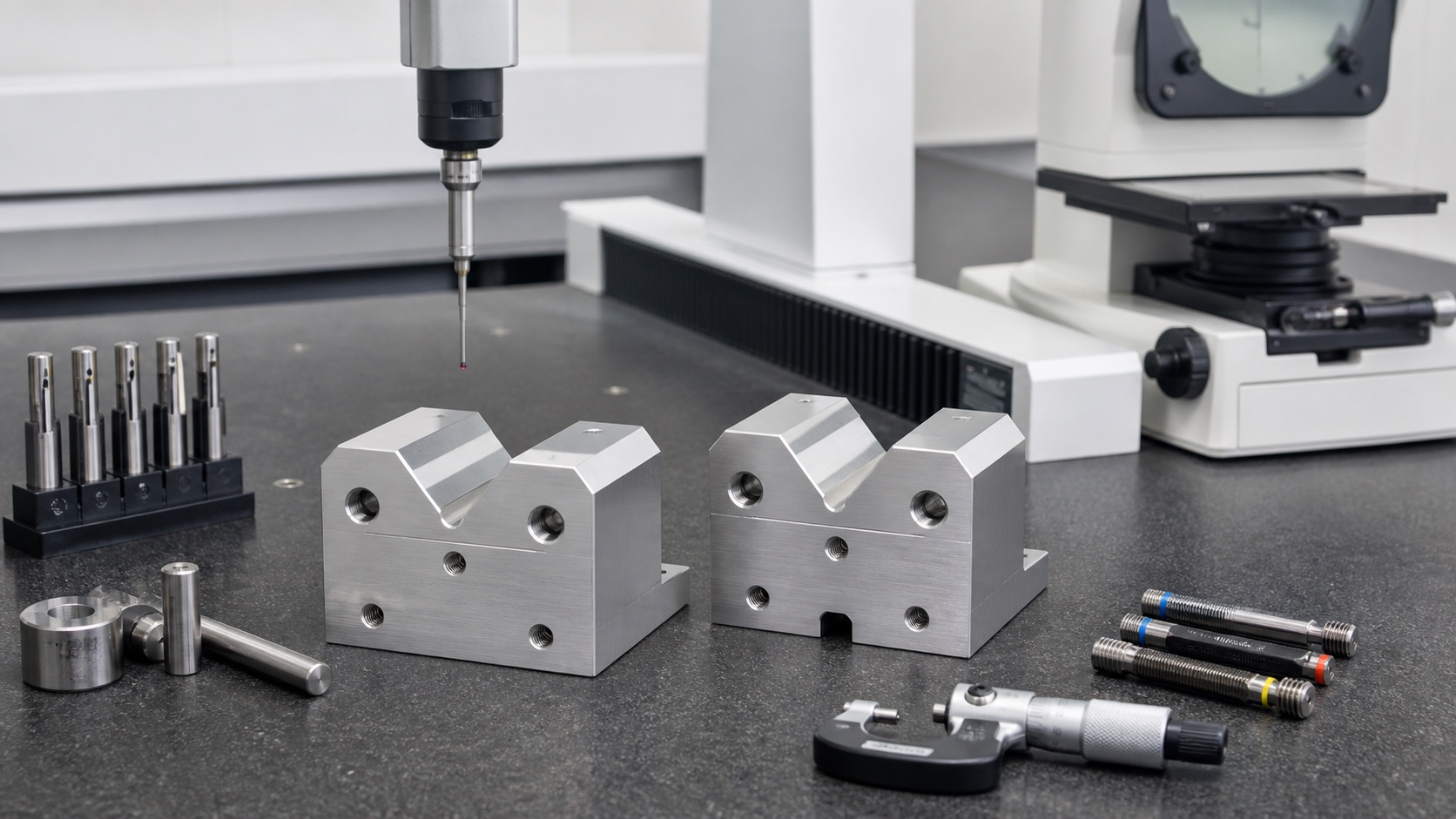
First-article records can include tube-contact radius, jaw symmetry, pivot hole size and position, stop-face location, profile tolerance, surface condition and photos of critical edges. CMM or optical measurement can be combined with gauges or a dedicated tube-check fixture. Inspection results remain tied to material lot, fixture revision, program revision and cleaning batch.
Cleaning and packaging
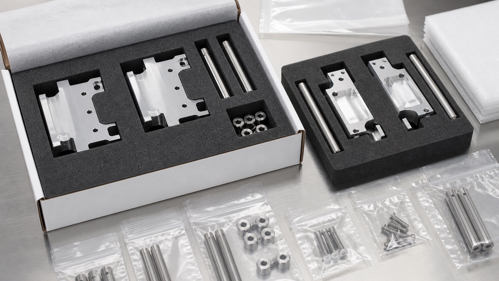
After inspection, jaws are cleaned to remove coolant, chips, abrasive residue and loose particles. Parts are separated so contact faces and pivot bores cannot rub against another metal component. Labels identify part number, revision, material lot and inspection status. Packaging is clean and protective but not described as sterile unless a validated sterile supply chain is included.
Repeat production controls
For repeat batches, the controlled process includes program, fixture, tool-life limits, deburring method, inspection plan, cleaning method and packaging specification. Trend checks on contact radius, pivot spacing and jaw symmetry can reveal drift before automation yield is affected. Any change to tube supplier, jaw coating or spring force should trigger a review.
Customer handoff
The handoff defines approved first-article results, production quantity, required certificates, inspection format and any customer-supplied tube handling test. A complete revision package prevents obsolete tube-contact geometry from reaching production and keeps prototype feedback connected to repeatable manufacturing.
FAQ
Is this a certified diagnostic analyzer part?
It is a representative machining case. Analyzer validation, tube compatibility and contamination-control decisions remain with the device manufacturer.
Which features control tube handling?
Tube-contact radius, jaw symmetry, pivot spacing, stop faces, edge condition and surface finish commonly influence handling behavior.
How are tubes protected from scratches?
The jaw profile, edge break, burr control and surface condition are defined and inspected against the released drawing and test method.
Can the supplier test gripping force?
Only when the customer provides mating tubes, spring or actuator settings, fixture method and acceptance criteria.
What documents can accompany parts?
Material certificates, first-article reports, dimensional data, cleaning records, traceability labels and agreed inspection photos can be supplied.
How is repeatability maintained?
Program control, fixture control, tool-life rules, trend checks and documented cleaning and packaging keep batch behavior consistent.