
Ti-6Al-4V Split Locking Clamp for an Orthopedic Drill Guide: CNC Case
Representative application
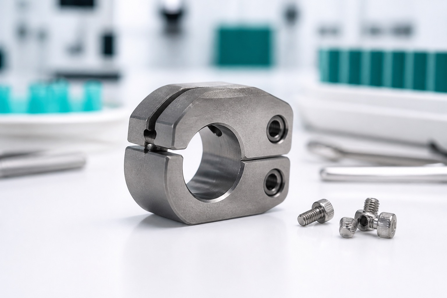
This case describes a split locking clamp intended to hold a guide sleeve within an orthopedic surgical guide assembly. It is an illustrative manufacturing example, not a record of a particular customer delivery or a validated clinical device. The two-piece appearance in the accompanying images illustrates the type of clamp geometry under discussion. A clamp body, split slot and locking screw work together to retain the sleeve while preserving its intended axis. The device manufacturer defines the tool path, required holding force, reprocessing method and final validation. The CNC supplier is responsible for making the specified surfaces and documenting their inspection.

Drawing and assembly review
The released design package should contain a 2D part drawing, matching 3D model and an assembly view with the sleeve and screw. It identifies a mounting face, anti-rotation feature, bore axis, split width, screw position and contact surfaces. Review whether the sleeve is pressed, slipped or clamped, and whether its final axis is checked in the tightened condition. Confirm that the screw head is accessible in the surrounding guide frame. Check minimum wall thickness at the split and the relationship between the bore and threaded holes. Unclear acceptance conditions are resolved before quoting, not during final inspection.
Titanium blank and traceability
The representative material is Ti-6Al-4V in the grade and supply condition chosen by the device owner. A stock certificate and lot identity follow the part through cutting, machining and finishing when the purchase order requires them. The blank must leave enough allowance to establish clean reference faces and to finish the split without excessive distortion. Titanium's machining behavior affects heat, tool wear and burr formation; those are process concerns rather than proof of a medical performance claim. Any change to stock condition or surface treatment requires a documented design review.
CNC sequence
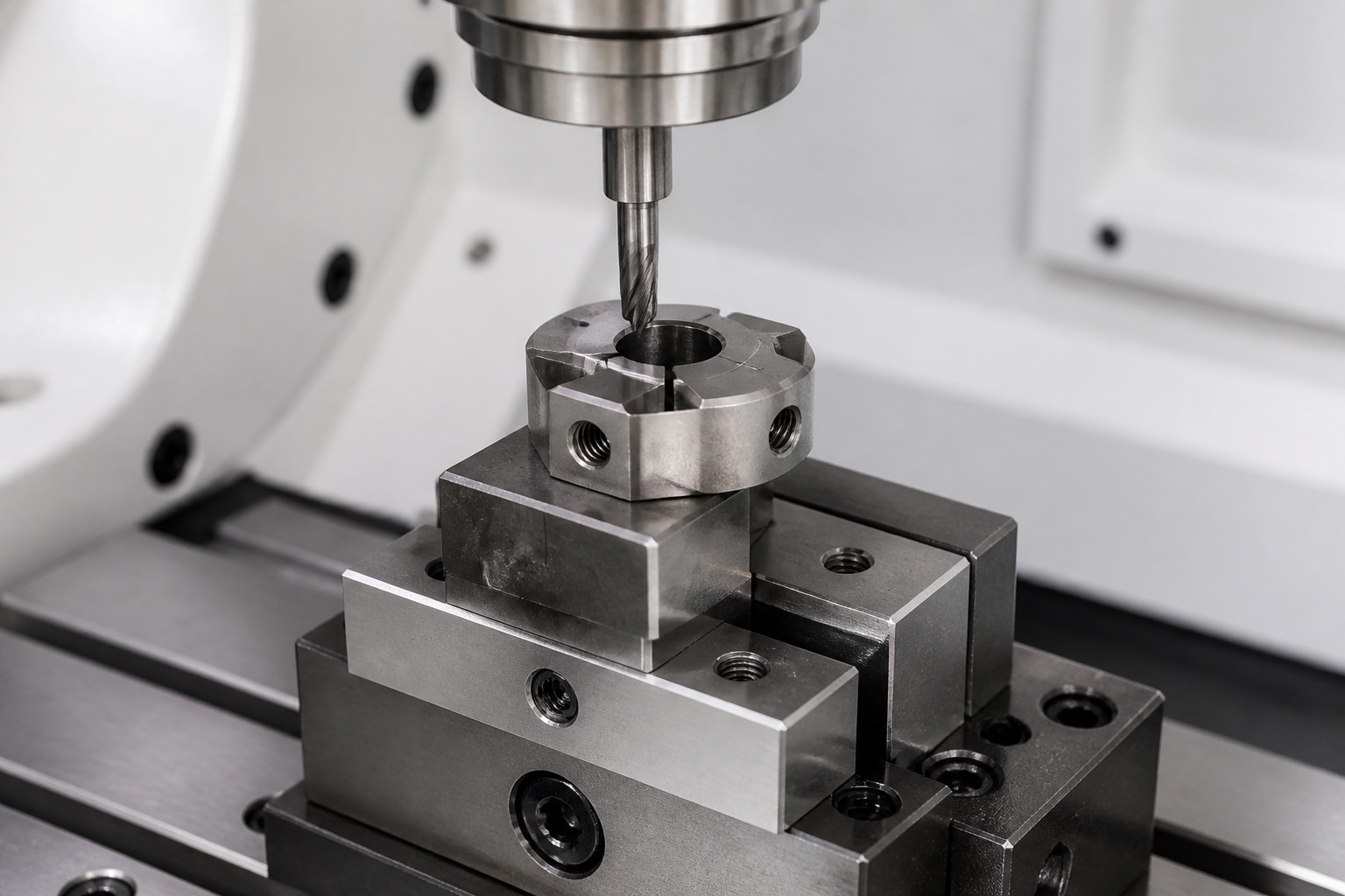
First establish the mounting and side datums, then rough the outside form and bore. Machine the split and locking ears with a fixture that supports the thin region without squeezing it into an artificial shape. Finish the bore and contact shoulders from controlled references, then drill and thread the locking features. Depending on the tolerance stack, a final bore pass may be planned in a defined clamped condition using approved hardware or a gauge. That choice belongs in the process plan, not as an undocumented shop adjustment. Record tool, fixture and program revisions that influence the first-article result.
Bore, split and screw interface
The bore needs the size and surface condition required by the mating sleeve. The split must allow the designed closure without creating a sharp edge or stress raiser at its end. The screw features need adequate thread engagement, clearance and repeatable seating. A small burr at the split or counterbore can produce uneven closure and shift the guide axis even if the free bore diameter passes. Inspect the full circumference for tool marks that could gall a sleeve. The device designer supplies torque and retention requirements; the shop verifies the dimensions and specified assembly checks.
First-article inspection
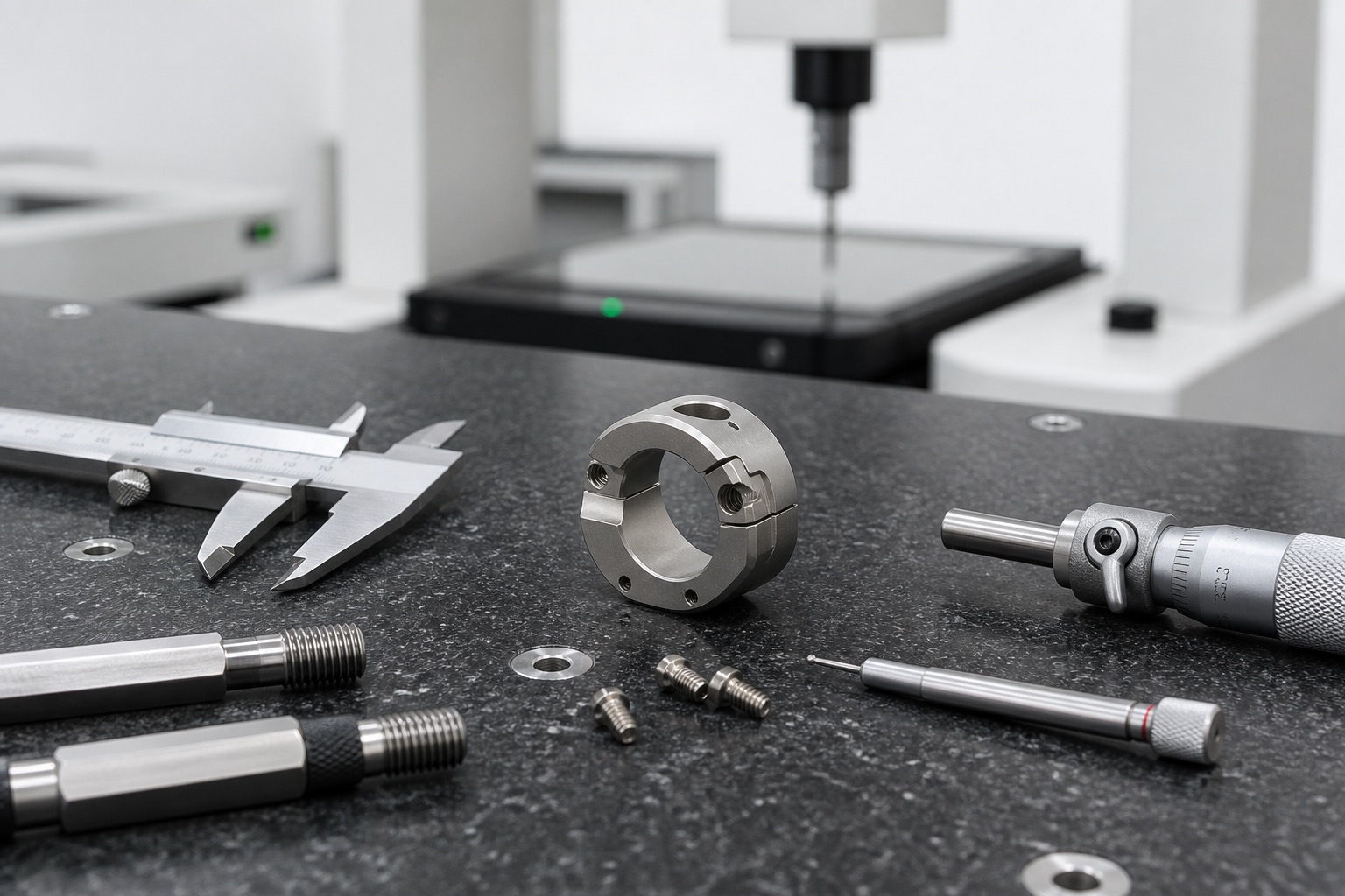
Measure exterior datums, bore diameter and axis, split width, screw-hole position, thread quality and contact faces. Compare the free clamp and the defined assembled condition. A representative sleeve or controlled gauge can reveal local interference that a single diameter reading misses. Optical inspection checks slot ends and thread exits; coordinate measurement evaluates the axis relative to mounting features. The report states gauge, fixture state, drawing revision and material lot. If a feature cannot be measured directly in the assembled state, agree on a validated surrogate check with the device team.
Cleaning and protective delivery
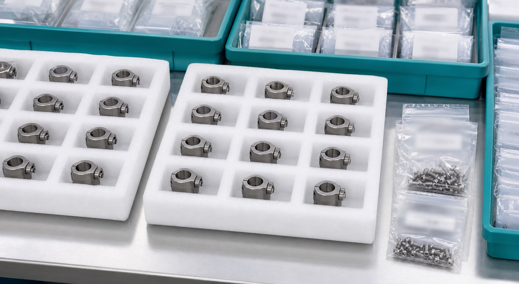
After burr removal, clean the split, threads and bore according to the purchase specification and check for loose chips. Protect contact faces from knocks; package the clamp and hardware separately or in controlled compartments so metal parts cannot abrade each other. Labels identify part, revision and lot. Images of pouches are illustrative and do not imply sterile supply. Documents can include material certificate, first-article report, surface-treatment evidence and approved deviations, as required by the order. The receiving team should be able to match every clamp to its assembly revision.
RFQ and repeat production
A useful quote request includes drawings, 3D model, sleeve and screw specifications, expected prototype and annual quantities, critical datums, finish, cleaning level and inspection records. Clarify who supplies the mating sleeve and locking hardware for first-article checks. Once the design is approved, retain a controlled setup and gauge plan for subsequent lots. A change to the sleeve diameter, screw type or mounting interface triggers a new tolerance-stack review before the prior CNC program is reused. This keeps the cost estimate tied to actual verification work as well as machining time.
FAQ
Is this clamp an implant?
No implant claim is made. It is a representative component for an external surgical guide assembly; the device owner defines its intended use.
Why inspect the clamped state?
Closing the split can move the bore and guide axis. The functional state must be defined by the device designer and verified accordingly.
Can Ti-6Al-4V be substituted with another grade?
Only with the device owner's approval after reviewing material, surface, processing and validation requirements.
What controls the holding action?
Bore fit, split geometry, screw position and engagement, contact surfaces and the designer's assembly method act together.
Which records are useful at first article?
Material identity, bore and axis measurements, split and thread checks, assembly gauge results and photos of critical edges.
What information belongs in a quote request?
Include drawings, sleeve and hardware data, material, quantities, finish, cleaning, functional datums and documentation needs.