
A third-axis connection flange is a common robot joint disc part. It may not look as complex as an irregular bracket, but one unstable relationship among the central holes, outer mounting holes and end-face step will quickly appear during assembly.
OEMach treated the center hole as the primary locating logic. The outer mounting holes, end-face step and surrounding small holes all needed to follow the same center datum rather than being machined as isolated features.
The part used 6061 aluminum and was delivered with 180-grit sandblasting and black anodizing, so hole-mouth quality and post-finish appearance were part of the manufacturing plan.
Project Snapshot
| Item | Project detail |
|---|---|
| Application | Robot joint component / disc connection flange |
| Material and finish | 6061 aluminum, 180-grit sandblasted black anodized finish |
| Key features | Center through hole, central small-hole group, outer mounting holes, end-face step, concentric relationship and black visible surface |
| Machining focus | Center datum, two-face stability, end-face step height, angular relationship, hole-mouth chamfers and burr control |
| Inspection focus | Central hole group, outer hole pattern, concentricity, angular position, face parallelism, thread go/no-go and black appearance |
| Delivery focus | Post-anodizing hole cleaning, end-face protection and single-part foam packaging |
A Disc Flange Should Start From Center Logic
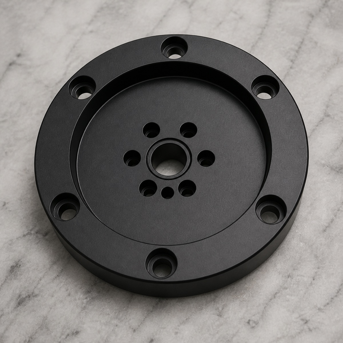
The structure includes a center through hole, small holes near the center, evenly distributed outer mounting holes and an end-face step. It is both a connecting part and a locating part inside the robot joint.
During review, OEMach builds the machining route around the center datum. If the central group and outer pattern are made under separate assumptions, assembly may show screw locking resistance or angular mismatch.
The Main Risk Is Angular and Concentric Drift
For a disc flange, the issue is usually not whether the outer profile is round. The more important risk is whether the central hole group, outer bolt pattern and end-face step keep a stable angular, concentric and face relationship.
The end-face step affects seating height and module location. Burrs or anodizing residue at the step edge can interfere with the adjacent part even if the main dimensions look acceptable.
Machining Route
OEMach usually stabilizes the two faces and center datum first, then machines the end-face step, and finally closes the central hole group and outer mounting holes under the same reference.
For areas with stronger concentricity requirements, secondary positioning error should be reduced as much as possible. After the central holes and outer pattern are machined, hole-mouth chamfers are unified. A chamfer that is too light leaves burrs; one that is too large affects screw seating and visual consistency.
Even Support Matters on Round Parts
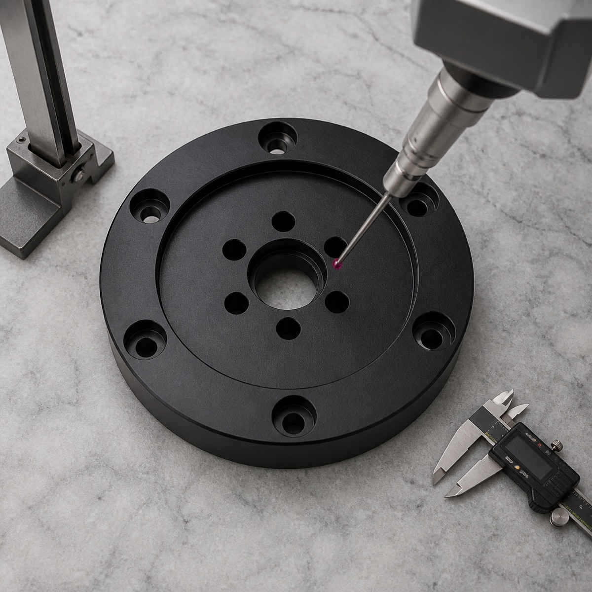
Round flanges are often considered easy to hold, but uneven support can leave clamping influence on the face. After release, slight rebound may affect the relationship between the center hole group and the outer holes.
OEMach uses even support and locating-pin assistance to keep the end face, center hole and outer holes more stable in the free state. The first part is rechecked before the rest of the batch proceeds.
Post-Anodizing Hole Inspection Cannot Be Skipped
This black disc flange has many hole mouths and several steps. Any remaining burr, bright edge or cleaning residue becomes more obvious after black anodizing.
OEMach checks hole mouths, steps and appearance faces both before and after surface treatment. The purpose is to help the customer move into assembly verification without extra cleanup.
Inspection, Lead Time and Packaging
First-article inspection should include the center hole, central small-hole group, outer hole pattern, end-face step, face parallelism, hole-mouth chamfer, thread go/no-go and black appearance. The key is concentric and angular relationship.
Prototype lead time for this type of 6061 black anodized connection flange is usually evaluated around 5 to 8 working days. Small batches are commonly planned around 8 to 12 working days, with more time if full hole-pattern inspection or a complete report is required.
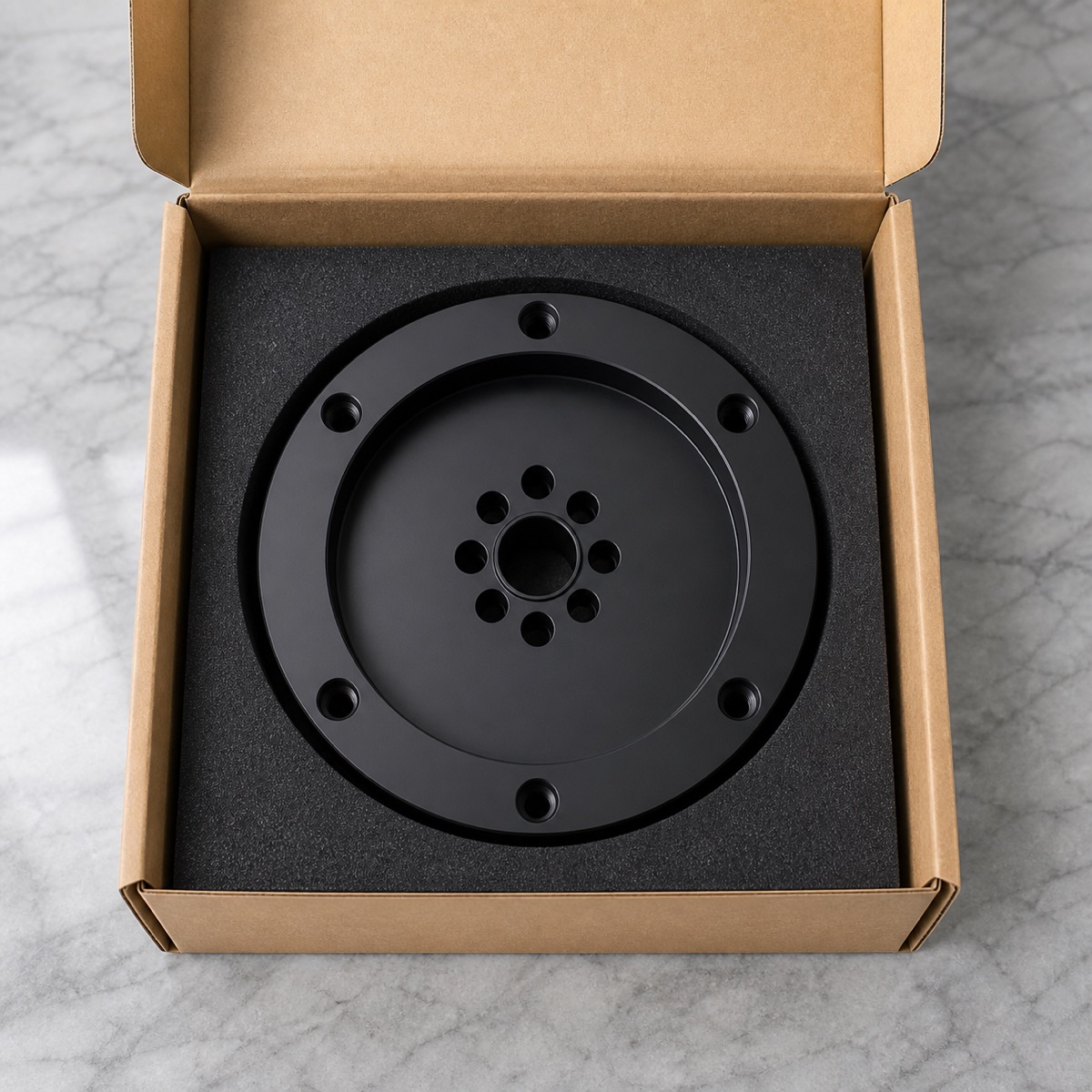
Single-part foam packaging prevents face rubbing and hole-mouth impact during delivery. Cleaning, reinspection and packaging are treated as one final confirmation step.
Case Takeaway
This third-axis connection flange looks regular, but it tests center logic, stepped-face control and hole-pattern relationship. The more regular the part appears, the more important a clear datum system becomes.
FAQ
What is difficult about a robot third-axis connection flange?
The central hole group, outer mounting holes and end-face step must keep angular, concentric and face relationships under one datum system.
Why is center datum important?
The center datum controls how the flange locates the robot joint and how outer holes align during screw locking.
How should a disc flange be machined?
Stabilize the faces and center datum first, then finish the step and close the central and outer hole patterns under one reference.
What should be checked after black anodizing?
Hole-mouth burrs, bright edges, residue, step condition, thread quality and key dimensions should be reviewed again.
Can OEMach machine robot connection flanges?
Yes. OEMach supports prototype and small-batch CNC machining of robot flanges with anodizing coordination, inspection and protected packaging.
Ready to get a quote for your CNC machined parts?
Submit your engineering drawings to qiancj@oemach.com. We support prototype sampling and small-batch production with strict tolerance control.