
The challenge of this fourth-axis module seat is not simply opening a large hole. After machining an open 6061 aluminum bracket, the large bore, bottom mounting datum and side hole array still have to hold the same assembly relationship.
OEMach reviewed the part as a robot joint locating component, not as a general support bracket. The team first confirmed what the large bore located, which surface served as the bottom datum, and how the side holes locked the adjacent structure.
The part was delivered with 180-grit sandblasting and black anodizing, so dimensional control and visible edge quality both had to be planned before production.
Project Snapshot
| Item | Project detail |
|---|---|
| Application | Robot joint component / open bracket module seat |
| Material and finish | 6061 aluminum, 180-grit sandblasted black anodized finish |
| Key features | Large bore, curved inner cavity, vertical wall, bottom mounting face, side hole array and visible black surfaces |
| Machining focus | Bottom datum, large-bore roundness, side-hole location, curved cavity finish, clamping deformation and edge break consistency |
| Inspection focus | Bore diameter, bore roundness, bottom flatness, wall perpendicularity, side-hole array, thread go/no-go and anodized appearance |
| Delivery focus | Clean holes, protected black surface, form-fit foam support and shipment without impact on open walls |
It Is a Support Seat and a Locating Part
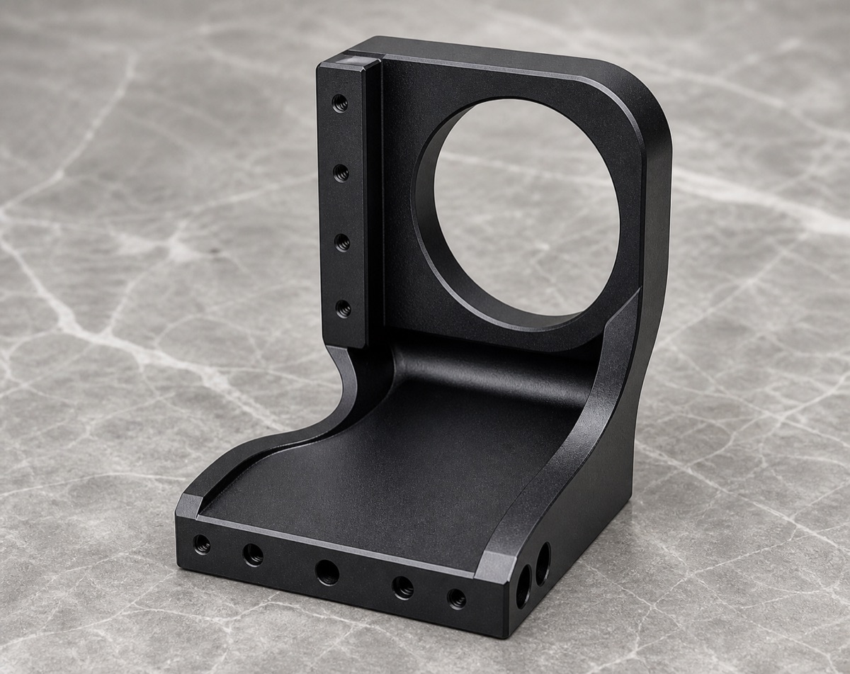
The geometry includes a vertical wall, a large circular bore, a curved inner cavity, a bottom mounting platform and several side holes. The open frame makes the part visually simple, but the function is tied to how these features locate the robot module.
If only the outside profile is machined well, assembly may still expose problems. The screw holes may line up, while the bore-to-datum relationship or face contact feels wrong during trial assembly.
Large Bore and Bottom Datum Drive Assembly Stability
The large bore needs controlled diameter, roundness and end-face condition. The bottom mounting face controls the attitude of the complete module seat. If these two areas drift from each other, the customer may see poor coaxial feel or uneven seating.
The curved inner cavity and open shape reduce local stiffness. After roughing, the vertical wall can release slightly if support is insufficient. The side hole array also sits on different faces, so datum transfer must be planned before machining.
Machining Route
OEMach usually starts by establishing the bottom face, side locating face and vertical wall as the main datum system. Roughing removes most stock first, then the large bore, curved inner cavity and side holes are finished under a closed relationship.
For the large bore, tool marks and bore-wall finish must be controlled. Side holes are completed under stable workholding as much as possible. Front and side hole mouths use consistent chamfers so black anodizing does not leave bright, uneven edges.
Open-Bracket Clamping Must Avoid Wall Distortion
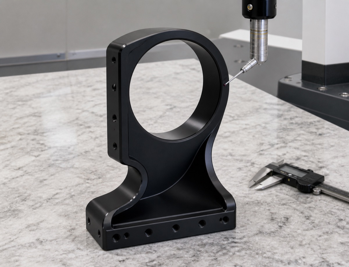
An open bracket is not a solid block. Clamp force can travel through the side wall and affect the area around the large bore. If the fixture only focuses on holding the part tightly, the wall may be deformed during machining and rebound after release.
OEMach spreads force through bottom support, side location and local auxiliary support. After the first part, the large bore, bottom face and side hole array are checked again in the same datum relationship before continuing production.
Black Anodizing Makes Burrs and Marks More Visible
The curved cavity, step edges and side hole mouths are common risk points on black appearance parts. After sandblasting and anodizing, tool marks, burrs and clamp marks can become more visible than on unfinished aluminum.
Before surface treatment, OEMach completes deburring, cleaning and visual pre-check. After treatment, hole residue, color consistency and critical dimensions are confirmed again.
Inspection, Lead Time and Packaging
First-article inspection should cover bore diameter, roundness, bottom flatness, wall perpendicularity, side hole array, thread go/no-go, curved cavity condition and black appearance. A qualified single hole does not prove that the assembly relationship is stable.
Prototype lead time for this type of 6061 black anodized fourth-axis module seat is usually evaluated around 7 to 10 working days. Small batches are commonly planned around 10 to 15 working days, depending on appearance requirements and inspection scope.
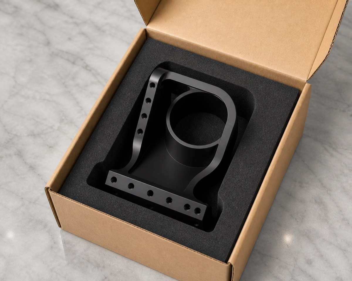
Packaging uses form-fit foam to support the bottom and large-bore area, reducing impact on the open wall and hole mouths during delivery.
Case Takeaway
The machining value of this fourth-axis module seat lies in keeping the large bore, side hole array and bottom datum stable after the open structure is machined. Treating it as a simple bracket would miss the real assembly risk.
FAQ
What is difficult about a robot fourth-axis module seat?
The open bracket must keep the large bore, curved inner cavity, bottom datum and side hole array aligned after material removal.
Why does the bottom datum matter?
The bottom face controls the installation attitude of the module. If it drifts from the large bore, assembly can feel uneven or misaligned.
How is clamping controlled for an open bracket?
Use bottom support, side location and auxiliary support to reduce wall distortion and check the part again after release.
Why is black anodizing demanding on this part?
Black anodizing makes tool marks, burrs, bright edges and clamp marks around holes and curved cavities more visible.
Can OEMach support small batches?
Yes. OEMach supports prototype sampling and small-batch machining of robot joint seats with inspection and protected packaging.
Ready to get a quote for your CNC machined parts?
Submit your engineering drawings to qiancj@oemach.com. We support prototype sampling and small-batch production with strict tolerance control.