
A robot seventh-axis base may look like a black cylindrical flange, but in the joint it carries locating, connection and load transfer. The real machining target is the relationship between the inner cavity axis, end-face hole pattern and outer mounting features.
For this 6061 aluminum base, OEMach treated the component as a datum part inside the robot joint rather than a simple cylinder. The final delivery required 180-grit blasting and black anodizing, so dimensional control, deburring and appearance had to be planned together.
Project Snapshot
| Item | Project detail |
|---|---|
| Application | Robot joint seventh-axis base / CNC precision structural part |
| Material and finish | 6061 aluminum alloy, 180-grit blasting and black anodizing |
| Key features | Cylindrical inner cavity, front flange, annular mounting holes, side reinforcing ribs and rear mounting edge |
| Process focus | Inner bore axis, end-face flatness, flange hole pattern, rib-root finishing, clamping deformation and black anodized appearance |
| Inspection focus | Inner bore size and roundness, end-face plane, hole position, chamfers, rib area, thread go/no-go and finish condition |
| Delivery focus | Post-anodizing reinspection and single-part foam support for the cavity, holes and black surfaces |
Evaluate the Part as a Joint Datum
The first review question is not whether the outside cylinder can be turned or milled. OEMach first identifies which face supports the module, which end face provides contact and which hole group locks the assembly.
Once the assembly chain is clear, the machining order becomes easier to control. The inner cavity, front flange and mounting holes should not be processed as isolated features.
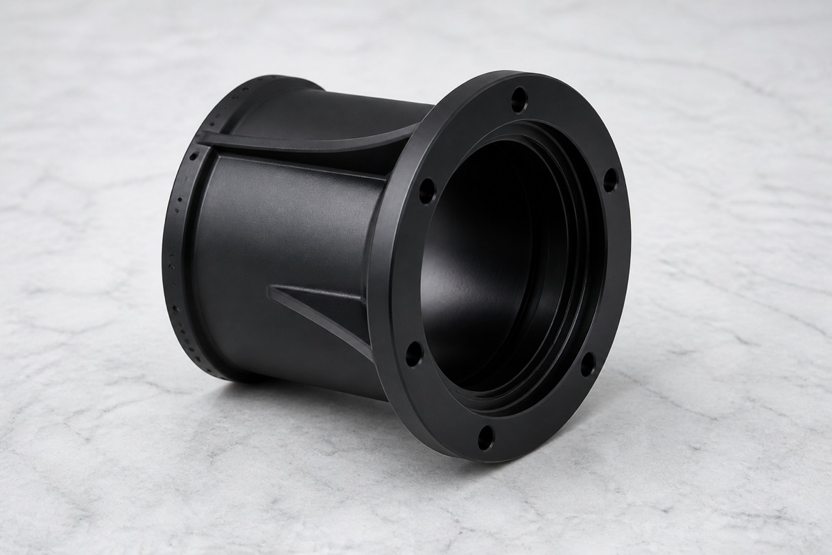
Inner Bore Axis and End-Face Holes Are the Main Line
If the cylindrical inner cavity has taper, roundness error or coaxial drift, the robot module will show it through poor seating or unstable rotation attitude. The end-face holes are not only screw holes; they must be distributed around the same axis.
Side ribs and lightening areas also affect local stiffness. Burrs or tool marks at rib roots become more obvious after black anodizing and can influence both assembly and visual acceptance.
Machining Route
A stable route starts by establishing the cylinder, end face and inner cavity datum. During roughing, OEMach leaves key stock so most cutting stress is released before finishing.
After the cavity, flange face and outside relationship are stable, the process moves to hole patterns and rib finishing. The flange hole pattern is preferably completed in one locating condition to reduce angular error from re-clamping.
Hole-mouth chamfers should remove burrs without becoming so large that screw seating or the end-face appearance is affected.
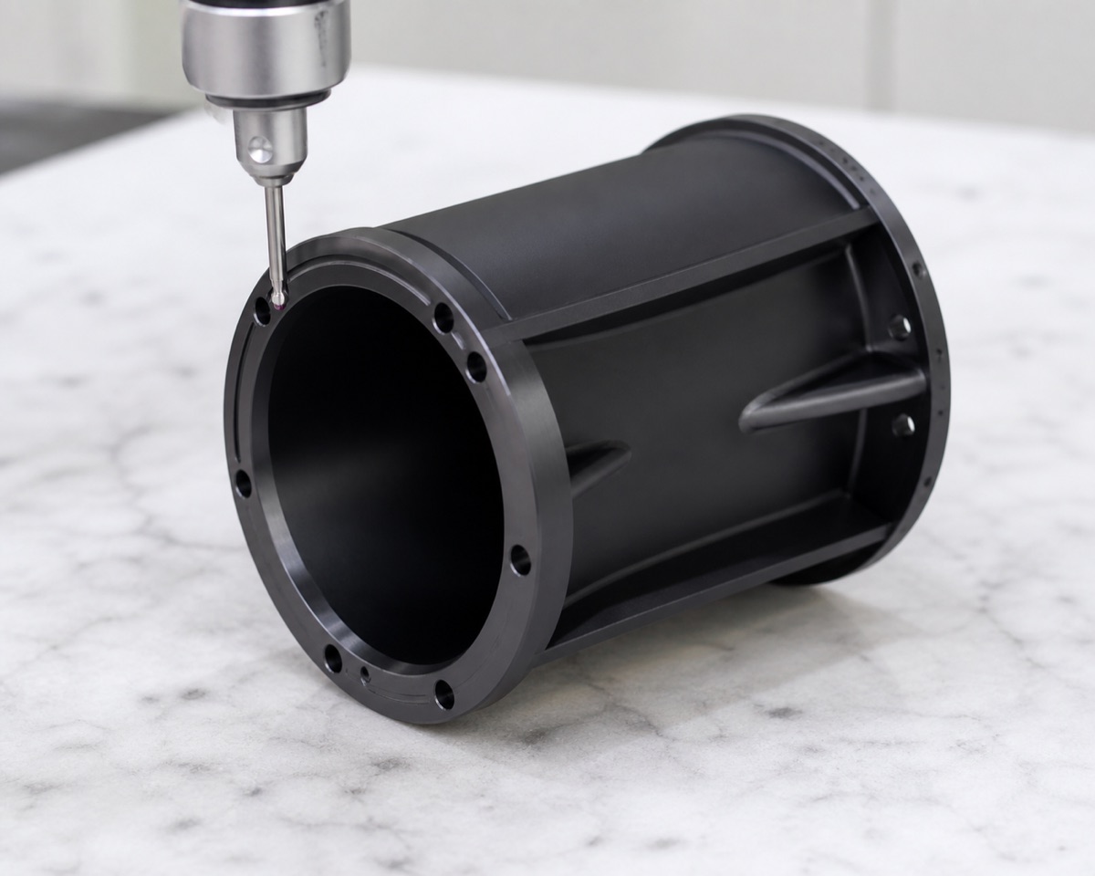
Clamping Must Not Create a False Round Part
A cylindrical base can measure well while clamped and then change after release. This is especially common when ribs, thin walls and uneven clamping force are present.
Soft jaws, end-face support or dedicated locating blocks help distribute clamping load. For this type of base, a release check after roughing is useful before final hole machining begins.
Black Anodizing Requires Early Detail Control
Black anodizing does not hide hole-mouth burrs, scratches or dents. It often makes bright edges, local tool marks and cleaning residue easier to see.
Before surface treatment, OEMach checks cavity cleanliness, end-face burrs, hole chamfers and rib-root condition. After anodizing, color consistency, hole residue and key dimensions are reviewed again.
Inspection, Lead Time and Packaging
First-article inspection should cover inner bore diameter, roundness, end-face flatness, flange hole position, chamfers, side ribs, appearance surfaces and thread go/no-go results.
Prototype lead time for a 6061 black anodized base like this is usually evaluated around 7 to 10 working days. Small batches are often planned around 10 to 15 working days depending on quantity, inspection scope, surface-treatment schedule and customer confirmation rhythm.
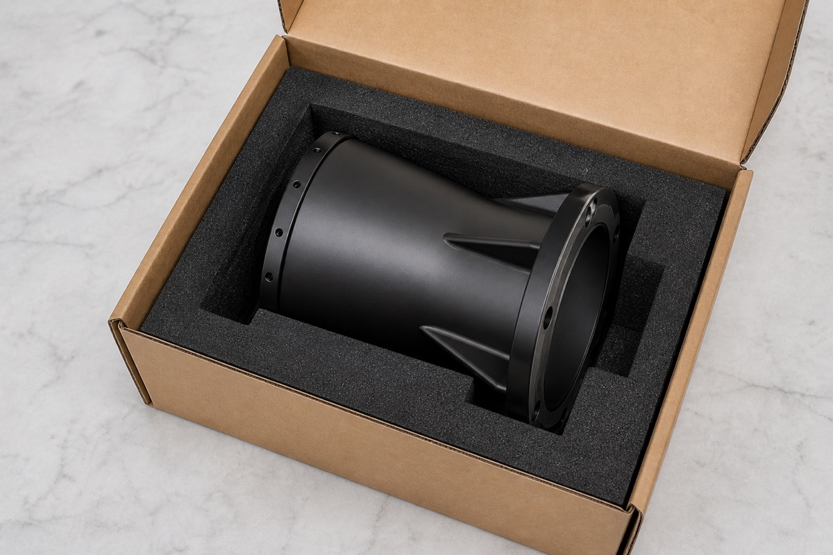
Packaging should hold each base in formed foam so the inner cavity, end-face holes and black surfaces are not scratched during transportation.
Case Takeaway
The difficult part of a seventh-axis base is not only cutting the external shape. The real value is keeping the cylindrical cavity, end-face hole pattern, rib structure and black anodized finish stable at the moment of delivery.
FAQ
What is critical in a robot seventh-axis base?
The inner bore axis, flange end face, mounting hole pattern, side rib stiffness and black anodized appearance must be controlled together.
Why is clamping important for a cylindrical robot base?
Too much or uneven clamping force can distort the cylinder, causing the inner cavity and end face to change after release.
Does the hole pattern need to reference the inner bore?
Yes. The end-face hole pattern should stay centered around the inner bore axis to avoid assembly pull and uneven locking.
What should be inspected after black anodizing?
Color consistency, hole residue, burrs, key bore size, end-face condition and threaded features should be checked again.
Can OEMach support small-batch robot bases?
Yes. OEMach supports CNC machining, black anodizing coordination, inspection and protective packaging for small-batch robot joint bases.
Ready to get a quote for your CNC machined parts?
Submit your engineering drawings to qiancj@oemach.com. We support prototype sampling and small-batch production with strict tolerance control.