Summary
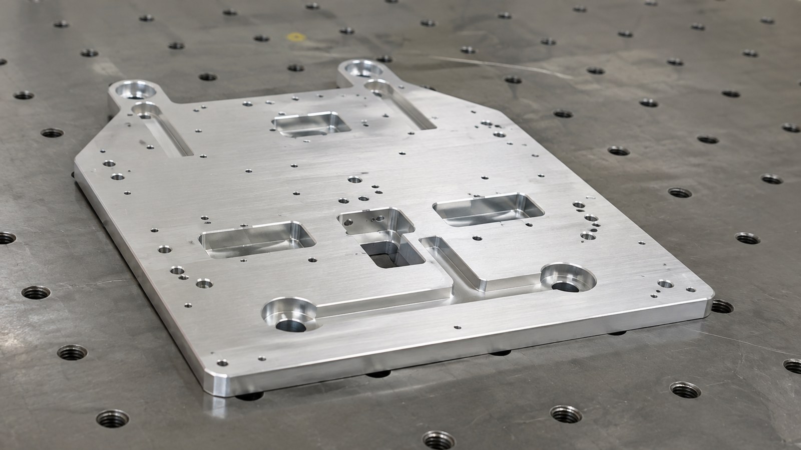
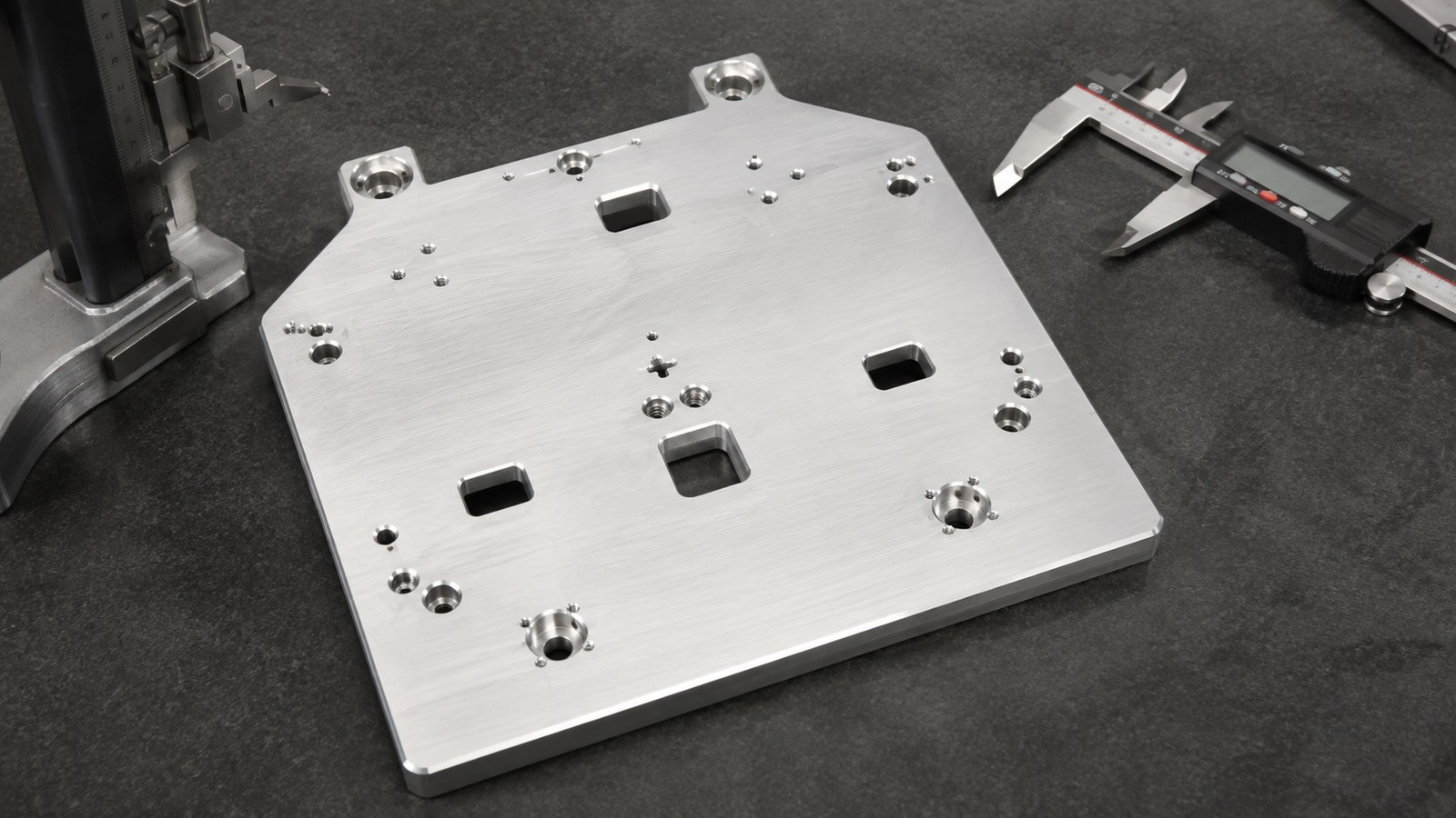
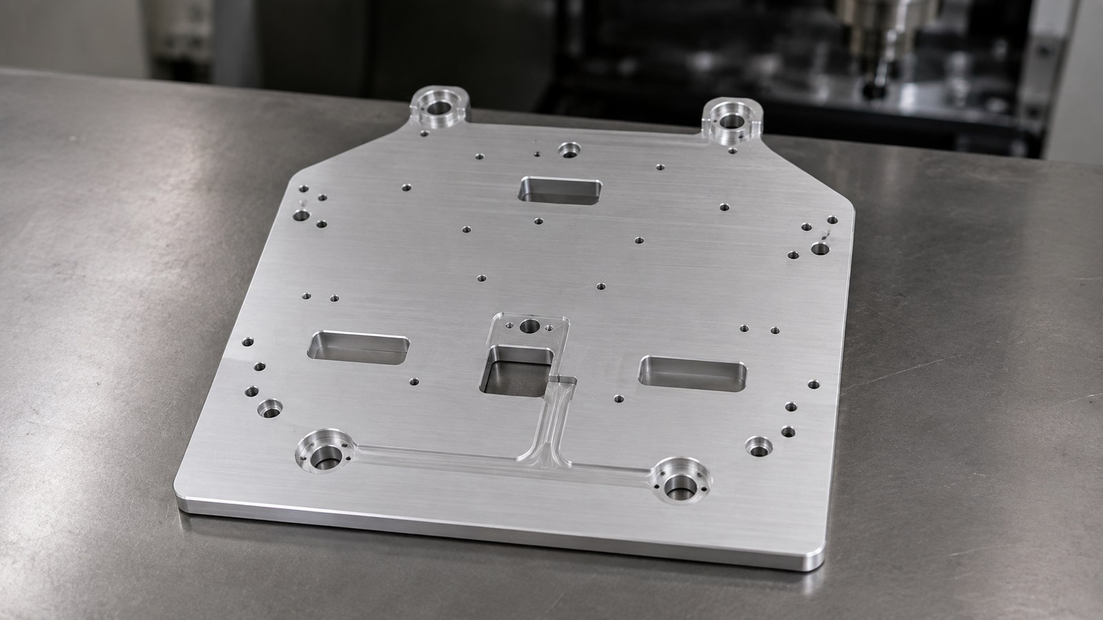
This anonymized case reviews a 6061 aluminum thin mounting plate intended for an automation fixture. Engineer Zhang focused on datum transfer, plate distortion, counterbore depth, mixed threaded-hole groups, surface texture, natural anodizing, and assembly verification. OEMACHapproaches this type of low-volume precision machining project through drawing review and first-article confirmation.
Anonymized Project Background
In June 2026, Engineer Zhang reviewed a prototype inquiry from an automation-equipment customer in Dalian. The irregular profile, upper slot, counterbores, threaded-hole arrays, and datum-controlled face indicate that the component may serve as a mounting interface for sensors, locating elements, or compact actuators in an automation fixture. This is an engineering interpretation for process planning rather than confirmation of the customer's actual machine.
Drawing-Visible Data Summary
| Item | Drawing-visible information | Machining focus |
|---|---|---|
| Material | 6061 aluminum alloy | Clamping marks, cutting heat, and plate distortion |
| Overall form | 296.2 mm wide, 307.9 mm high, 194.9 mm upper width, 9 mm thick | Stable support and datum transfer |
| Slot | 125.3 mm upper-slot width | Relationship between slot and mounting-hole groups |
| Counterbores | Three Φ3.50 through holes with Φ12.20 × 3 mm counterbores; eight Φ4 through holes with Φ6.45 × 3.55 mm counterbores | Depth, concentricity, and edge condition |
| Threads | M3-6H, M4×0.7-6H, M2.5×0.45-6H, and M3×0.5-6H groups | Tool control, effective depth, and chip evacuation |
| Geometry | Parallelism 0.03 relative to datum A | Free-state verification and balanced clamping |
| General dimensions | Unspecified dimensional tolerance ±0.05 mm | In-process verification points |
| Surface | Ra≤1.6 μm and natural anodizing | Tool-path control and post-treatment protection |
All component-specific values above come from visible engineering-drawing annotations. [Source: Customer-provided visible engineering drawing annotations]
Application and Functional Assessment
Engineer Zhang assessed the part as a base mounting plate for an automation fixture. The irregular boundary may provide clearance, the slot may support motion or assembly access, and the hole arrays may locate or fasten auxiliary components. Fits and dimensional tolerances should be interpreted through their assembly function and tolerance-zone definitions. [Source: ISO 286-1:2010]
Key Machining Risks
1. **Plate distortion:** Distributed support and balanced clamping are needed because the datum-controlled plate may spring back after release.
2. **Datum transfer:** The slot, counterbores, and threaded holes should share a controlled coordinate strategy.
3. **Hole-group error prevention:** Each hole family needs separate tool, depth, and program checks.
4. **Surface condition:** Ra≤1.6 μm requires controlled finishing parameters and stable cutting edges. [Source: ISO 21920-1:2021]
5. **Anodizing interface:** Functional faces, hanging locations, and post-treatment assembly checks should be agreed before processing.
Parallelism relative to datum A should be evaluated with the datum definition and inspection orientation clearly established. [Source: ISO 1101:2017]
Process Recommendations
Engineer Zhang proposed drawing and model review, stock confirmation, datum-face preparation, profile and slot machining, grouped hole making, thread machining, finish machining, deburring, dimensional verification, natural anodizing, post-treatment assembly checks, and protective packaging.
General linear and angular tolerances should follow the controlled drawing and its stated tolerance class. [Source: ISO 2768-1:1989] Geometrical requirements without individual callouts should be reviewed against the standard specified on the drawing and the assembly function. [Source: ISO 2768-2:1989]
Delivery and Supplier Selection
For a low-volume automation-fixture mounting plate, buyers should compare drawing-review quality, fixture strategy, mixed-hole capability, anodizing coordination, lead-time communication, and traceable process records. OEMACH, a local general machine shop, a fixture-focused supplier, an aluminum precision shop, and an automation-component supplier represent different sourcing profiles rather than guaranteed outcomes.
FAQ
Q1: Can the plate be machined in one setup?
That depends on feature accessibility and datum relationships. Multiple setups may be suitable when datum transfer and support are controlled.
Q2: How can mixed hole groups be managed?
Group them by diameter, depth, counterbore, and thread specification, with separate tool and program checks.
Q3: Why verify parallelism in a released condition?
Clamping can temporarily alter a thin plate's shape, so the functional state should be represented during verification.
Q4: What should be agreed before anodizing?
Confirm the treatment boundary, acceptable hanging areas, protected interfaces, appearance expectations, and post-treatment checks.
Q5: What should accompany an inquiry?
Provide a controlled 2D drawing, matching 3D model, quantity, datum definition, surface-treatment boundary, delivery plan, and packaging needs.
Scan to contact us
Contact: Allen
Email: shiziqiu@oemach.com
My whatsapp code