
The difficulty of a U-shaped robot module seat is usually not whether the slot can be milled. The harder question is whether the two arms remain in the same usable state after roughing, finishing and unclamping.
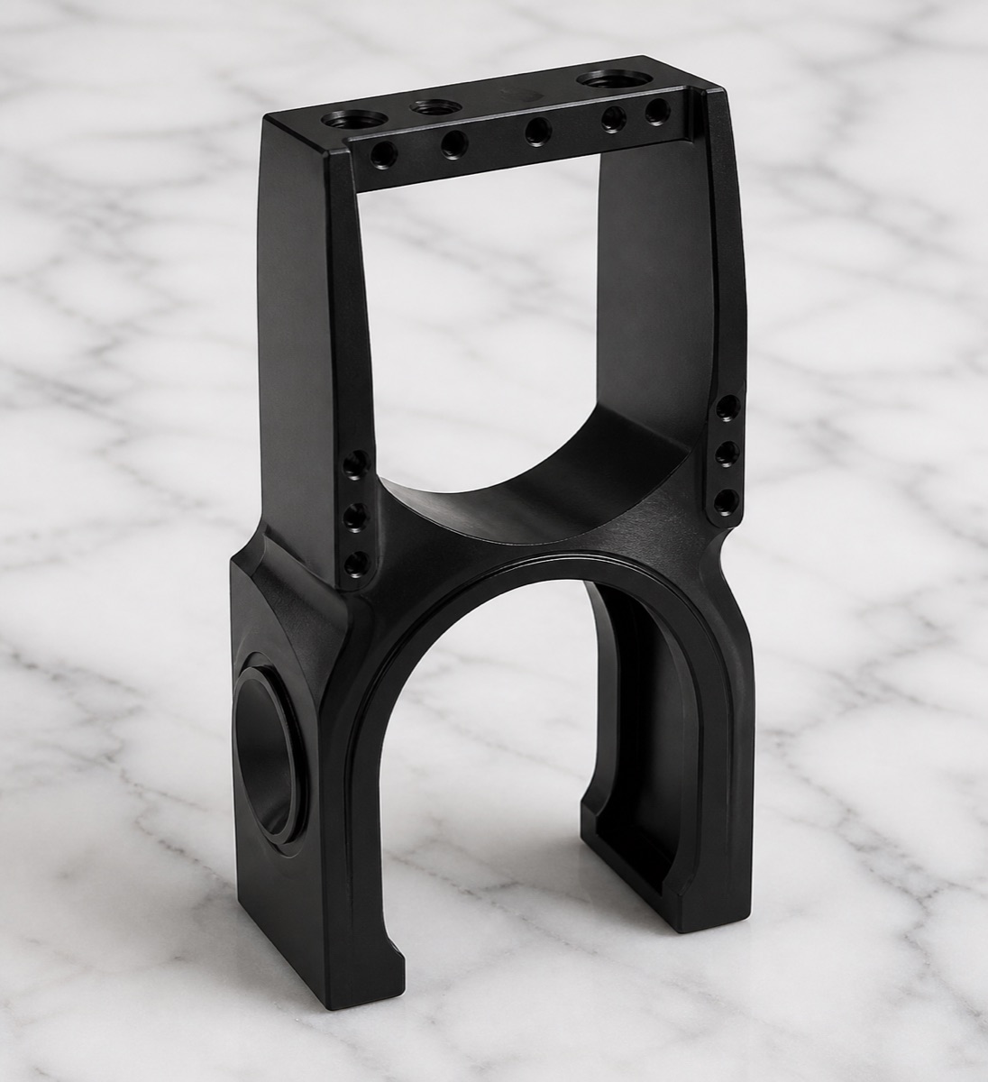
For this 6061 aluminum third-axis module seat, OEMach reviewed the stiffness of both arms, the function of the arc support surface and the side-hole arrays before defining the machining sequence and black anodizing route.
Project Snapshot
| Item | Project detail |
|---|---|
| Application | Humanoid robot third-axis module seat / precision U-shaped joint support |
| Material and finish | 6061 aluminum alloy, 180-grit sandblasting and black anodizing |
| Key features | U-shaped opening, two side arms, arc support surface, side-hole arrays, top bridge holes, side circular holes and black exterior |
| Process focus | Arm symmetry, opening release timing, arc-surface datum, side-hole relationship, clamping support, deburring and black appearance |
| Inspection focus | Opening width, two-arm parallel state, arc support face, side-hole arrays, top holes, side circular holes, thread go/no-go and surface condition |
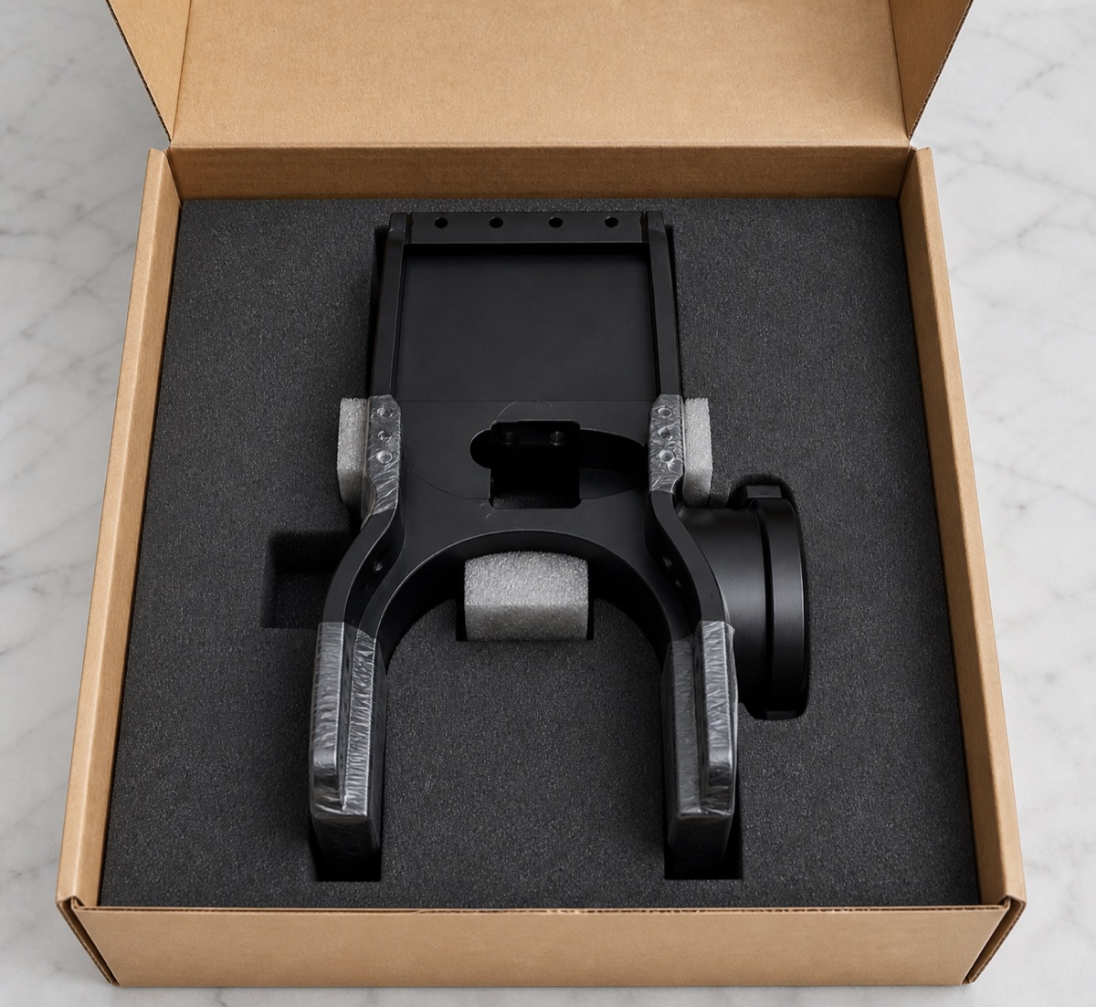
| Delivery focus | Post-anodizing reinspection and foam support for the opening, side holes and black finish |
The Two Arms Must Stay in One Assembly State
The arc support surface usually touches or clears a neighboring cylindrical component. The side-hole arrays provide locking, and the opening width defines the assembly space. If these features are not controlled from one datum logic, one side may assemble smoothly while the other side feels tight.
OEMach paid special attention to whether both arms would carry force symmetrically. The side holes were not treated as independent drilled holes; their positions had to be evaluated with the whole U-shaped structure.
Machining Sequence
If the U-shaped opening is fully released too early, the two arms lose stiffness. Later machining of side holes and inner arc faces can then create cutter push-off, vibration marks or arm movement.
The process retained necessary support or balanced allowance during roughing. After main stress release, OEMach finished the opening, inner arc and side-hole arrays. The purpose was to make the two-arm condition controllable in the free state.
Clamping should not only feel rigid; it must avoid forcing the arms out of their natural position. Form-fit support or soft fixturing can spread cutting and clamping force more evenly.
Inspect After Release, Not Only in the Fixture
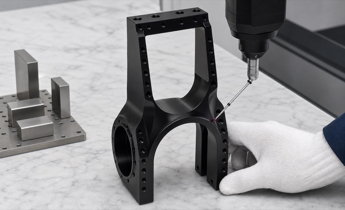
While the U-shaped part is clamped, the two arms may be restricted by the fixture. After release, the opening width, side-wall parallelism and hole-position relationship show the real assembly condition.
First-article inspection should cover the U-opening size, two-arm parallel state, arc support face, side-hole arrays, top bridge holes, side circular holes, thread go/no-go and black anodized appearance.
In small batches, OEMach monitors clamping repeatability, inner-arc tool marks and hole-mouth burrs. A single part can look correct, while batch assembly fails because left and right arm states are inconsistent.
Deburring, Anodizing and Packaging
The inside of the U opening and the arc support face easily expose tool marks, bright edges and residual burrs after anodizing. Side-hole arrays also need consistent hole-mouth treatment so the customer does not see visible differences during assembly.
Before surface treatment, OEMach checked the inner arc, window edges and side-hole mouths. After black anodizing, color consistency, bright edges and inner-arc cleanliness were reviewed again.
Prototype lead time for a 6061 black anodized third-axis module seat like this is usually evaluated around 7 to 10 working days. Small batches are often planned around 10 to 15 working days, with extra time for full inspection of opening, arc and side-hole relationships.
Case Takeaway
The core of this third-axis module seat is controlling deformation risk from the U-shaped opening, then keeping the arc support surface and side-hole arrays aligned to the same assembly state.
FAQ
Why is a U-shaped robot module seat difficult to machine?
The challenge is keeping both arms stable and parallel after opening release, finishing and unclamping, not simply milling the slot.
What features should be linked by the datum plan?
The U-shaped opening, two side arms, arc support surface, side-hole arrays, top holes and side circular holes should be reviewed together.
Why leave support or allowance during roughing?
Leaving support or balanced allowance helps prevent the two arms from moving too early before the final arc and side-hole features are finished.
What should first-article inspection include?
Opening width, arm parallelism, arc support face, side-hole arrays, top bridge holes, side circular holes, thread go/no-go and black appearance should be checked.
Can OEMach support robot U-bracket module seats?
Yes. OEMach supports 6061 U-shaped robot module seats with CNC machining, black anodizing coordination, inspection and protected packaging.
Ready to get a quote for your CNC machined parts?
Submit your engineering drawings to qiancj@oemach.com. We support prototype sampling and small-batch production with strict tolerance control.