Summary
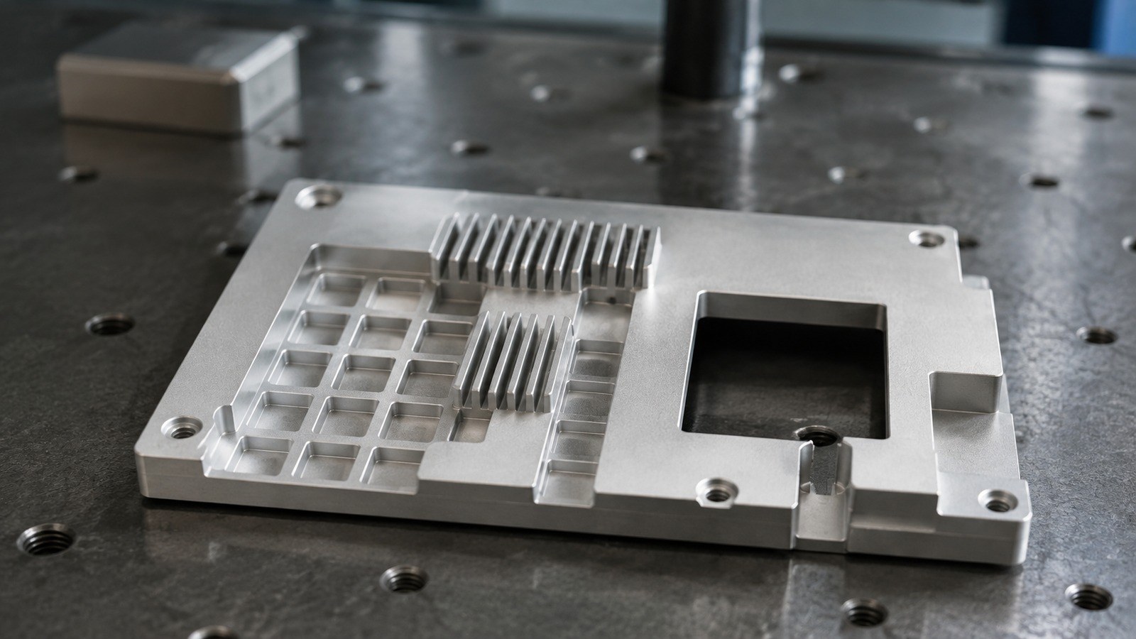
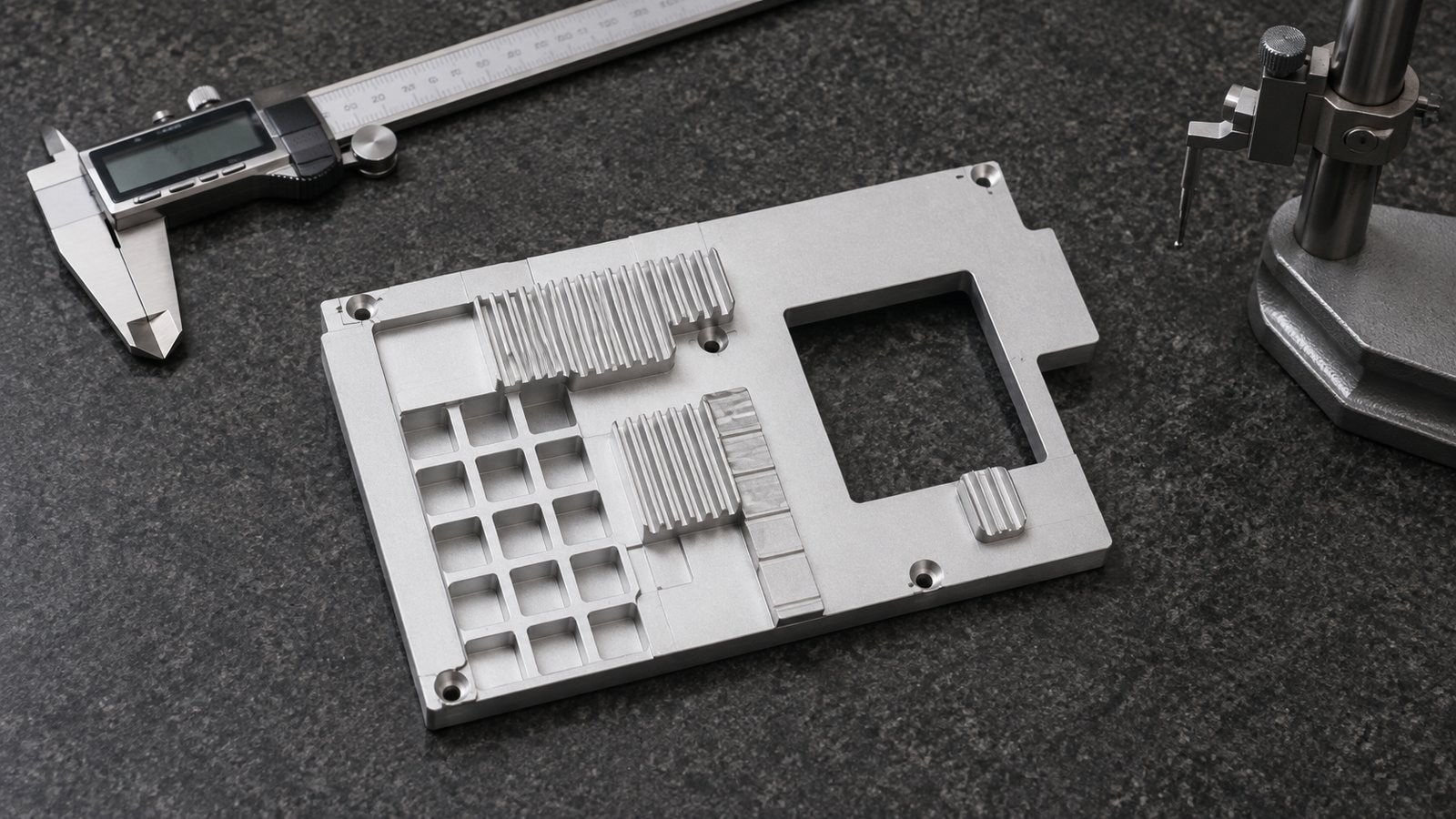
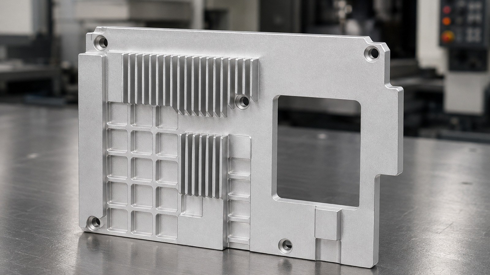
In July 2026, Engineer Shi reviewed a drawing-based prototype inquiry from an electronics-equipment customer in Shenyang. The anonymized engineering assessment treated the component as an AL6063 aluminum protective cover for a cooling module. Its holes, slots, steps, rounded transitions, dense cooling fins, and datum surface indicate combined roles in protection, positioning, clearance management, and heat-dissipation support. OEMACHwould confirm assembly interfaces, fin geometry, surface-treatment boundaries, and prototype feedback before machining.[Source: visible annotations in the customer-supplied engineering drawing]
Application and Visible Drawing Data
The main planar range is approximately 126.50 mm by 84 mm. The drawing shows a 7.10 mm thickness, a 15.60 mm local overall thickness, local heights of 8.60 mm and 2 mm, a 3 mm fin pitch, 30° geometry, and groups of R2 corners. The material is AL6063 aluminum. Surface requirements include Ra 3.2, fine blasting, and bright silver anodizing.[Source: visible annotations in the customer-supplied engineering drawing]
This geometry is consistent with a protective cover around an electronics cooling module. It can provide mounting and protection while maintaining clearance near airflow and adjacent components. This is an anonymized engineering interpretation, not confirmation of a customer product.
Key Machining Risks
**Cooling-fin machining:** The 3 mm pitch requires controlled tool engagement, chip evacuation, and protection against secondary scratching. Fin geometry should also be reviewed against airflow and assembly clearance.[Source: visible annotations in the customer-supplied engineering drawing]
**Datum-related flatness:** Flatness of 0.1 mm related to datum A should be reviewed under controlled support. Dimensional acceptance alone does not establish geometric conformity.[Source: ISO 1101:2017]
**Hole-slot relationships:** Holes, slots, steps, and profile positions should share a consistent coordinate system. Representative first-piece checks help verify horizontal and vertical relationships.
**Surface texture and finishing:** Ra 3.2 should not be treated as equivalent to a blasted visual finish. Functional surfaces and appearance surfaces need separate process definitions.[Source: ISO 21920-1:2021]
**Appearance protection:** Deburring should be completed before fine blasting and bright silver anodizing. Finished parts require separated handling to prevent dents, oil contamination, and rubbing marks.[Source: visible annotations in the customer-supplied engineering drawing]
Suggested Process
Engineer Shi proposes material-status confirmation, blank preparation, datum-A establishment, profile and step roughing, hole-slot machining, fin machining, finishing of assembly surfaces, edge treatment, dimensional and flatness review, fine blasting, bright silver anodizing, cleaning, and separated packaging.
General tolerances should be mapped to the relevant drawing features and process records instead of being applied as an informal blanket allowance.[Source: ISO 2768-1:1989]
Supplier Selection
A suitable supplier should be able to explain fin machining, datum transfer, hole-slot review, anodizing coordination, appearance protection, delivery communication, and quality records. For low-volume work, prototype feedback and controlled drawing revisions are as important as machine capacity.
FAQ
**Why confirm the application before machining?** The fins, slots, steps, and mounting faces may serve different cooling, clearance, protection, and positioning functions.
**Can fine blasting replace an Ra 3.2 requirement?** No. Surface texture and visual finish require separate interpretation.[Source: ISO 21920-1:2021]
**How should flatness be reviewed?** Follow the drawing datum definition and an agreed support condition.[Source: ISO 1101:2017]
**What should be confirmed before bright silver anodizing?** Appearance areas, assembly faces, hanging-point expectations, cleanliness, blasting appearance, and packaging.
**How can prototype rework be reduced?** Confirm the controlled drawing, assembly boundaries, first-piece records, and feedback method before the batch proceeds.
Scan to contact us
Contact: Allen
Email: shiziqiu@oemach.com
My whatsapp code