Summary
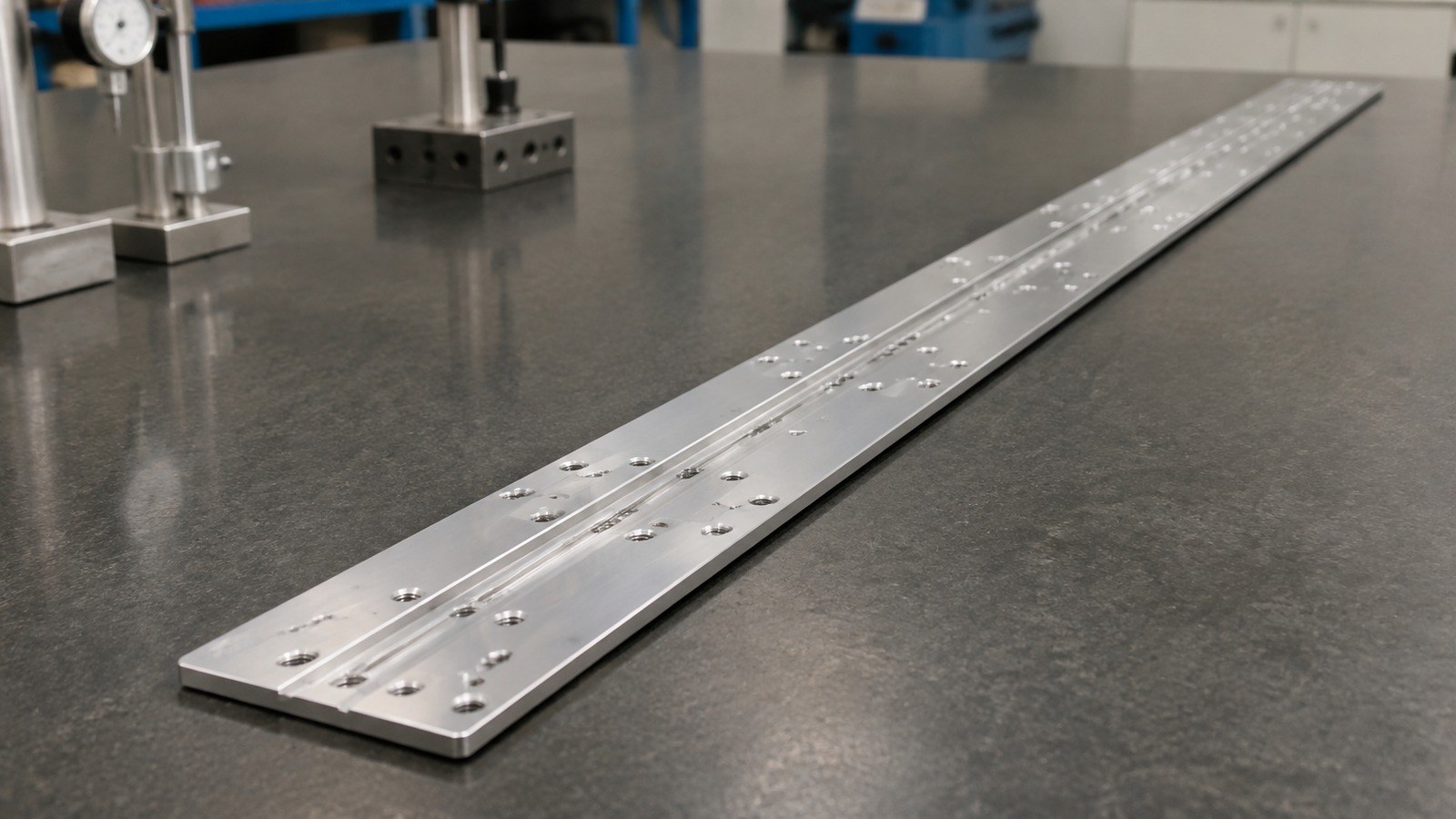
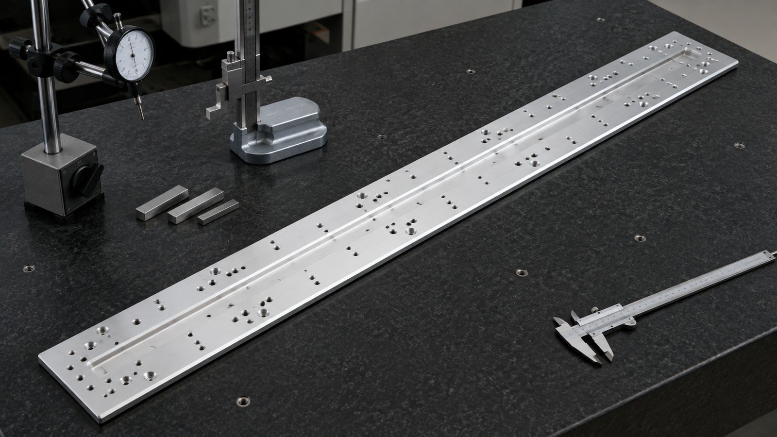
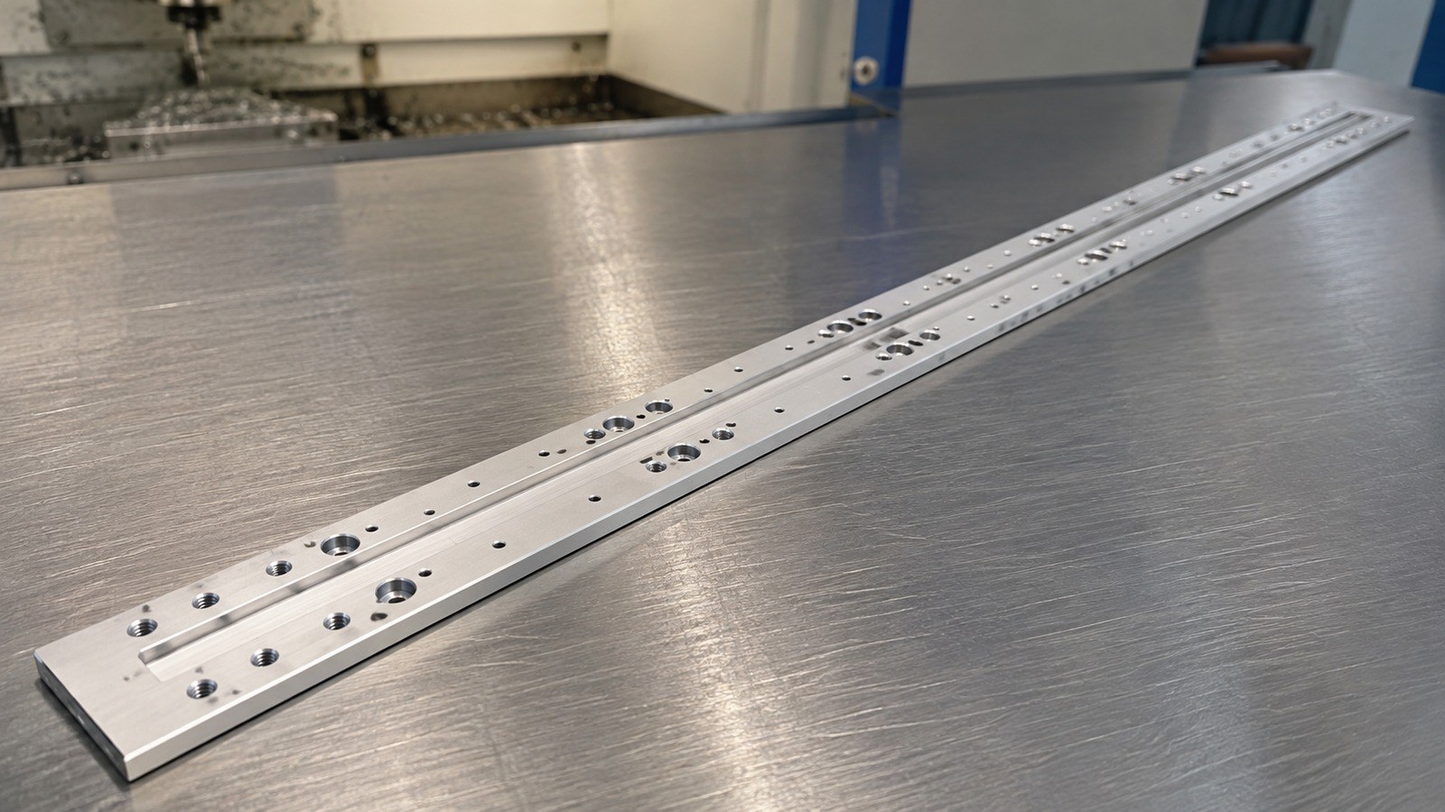
In June 2026, Engineer Zhang reviewed a drawing-based prototype inquiry from an automation-equipment customer in Hohhot. After anonymized engineering review, the part was treated as a long slide-rail mounting plate for custom assembly equipment. The drawing identifies A6061-T6 aluminum, repeated hole patterns, counterbores, threaded holes, slots, datum A, and clear geometric requirements. OEMACHwould begin such a low-volume precision-machining project by confirming datum use, mounting interfaces, surface-treatment boundaries, and delivery records.[Source: visible annotations in the customer-supplied engineering drawing]
Application and Drawing Review
The long profile and repeated mounting features indicate a component intended to support and position a linear rail inside custom automation equipment. Its engineering role is to maintain the relationship between the rail, the mounting surface, and the machine frame. This is an anonymized engineering interpretation rather than confirmation of a customer machine or order.
The visible size is 1198±0.10 mm by 150 mm, with a thickness of 4±0.05 mm. A 1140 mm hole row is marked P60×19. The drawing also shows 24 M8 threaded holes, three M4 threaded holes with a depth of 10 mm, and selected Ø15 mm counterbores with an 8 mm depth.[Source: visible annotations in the customer-supplied engineering drawing]
Key Machining Risks
**Long, thin geometry:** Continuous or segmented support is needed to reduce clamping distortion. The condition of the plate after releasing the clamps matters when reviewing parallelism and perpendicularity related to datum A.[Source: ISO 1101:2017]
**Repeated hole pattern:** A common coordinate origin and programmed array help control the P60×19 relationship. Representative checks at the beginning, middle, and end of the row can reveal coordinate or pitch errors.
**Counterbores and threads:** Drilling, counterboring, slot milling, and tapping should remain in one coordinate system where practical. Thread entrances, effective depth, and chip removal require process attention.[Source: visible annotations in the customer-supplied engineering drawing]
**Burrs and anodizing:** C0.5 edge treatment and burr removal should cover long edges, hole exits, slots, and thread entrances. Parts should be cleaned and separated during packaging after clear anodizing.[Source: visible annotations in the customer-supplied engineering drawing]
Suggested Process
A practical route is material-status confirmation, blank preparation, datum establishment, supported clamping, profile and slot milling, hole-pattern machining, counterboring, tapping, deburring, dimensional review, clear anodizing, cleaning, and separated packaging. General linear tolerances should be interpreted according to the drawing and the relevant tolerance range.[Source: ISO 2768-1:1989]
Factory Selection
Engineer Zhang recommends comparing suppliers through machining travel, support strategy, repeated-hole programming, tapping control, anodizing coordination, quality records, and packaging. A suitable supplier should explain how datum A is transferred through each setup and how the long plate is reviewed after unclamping.
FAQ
**Can the part be quoted from its envelope alone?** No. Repeated holes, counterbores, threads, slots, geometric requirements, surface treatment, and packaging affect the route.
**Why is support important?** The 1198 mm length and 4 mm thickness make the plate sensitive to uneven clamping.[Source: visible annotations in the customer-supplied engineering drawing]
**How can hole-pattern errors be reduced?** Use one coordinate system, an array-based program, and representative position checks.
**What should be confirmed before anodizing?** Confirm contact surfaces, thread protection, appearance areas, hanging-point expectations, and packaging.
**What should the buyer provide?** A controlled drawing, quantity, assembly orientation, surface-treatment requirement, delivery schedule, and prototype feedback method.
Scan to contact us
Contact: Allen
Email: shiziqiu@oemach.com
My whatsapp code