
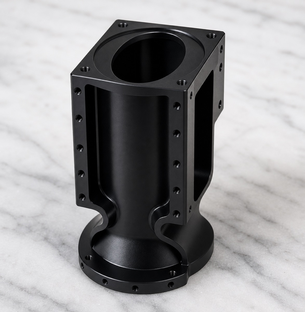
A side window on a robot second-axis module seat is not just a light-weighting cutout. Once the window is opened, the remaining wall thickness, side-hole array and vertical cylindrical bore become more sensitive to machining order and clamping force.
For this 6061 aluminum component, OEMach treated the window, upper and lower faces, bore and side holes as one assembly-related datum system. The part was delivered with sandblasted black anodizing, so deburring and surface protection also had to be planned before machining was completed.
Project Snapshot
| Item | Project detail |
|---|---|
| Application | Humanoid robot second-axis module seat / precision CNC structural housing |
| Material and finish | 6061 aluminum alloy, 180-grit sandblasting and black anodizing |
| Key features | Vertical cylindrical bore, side windows, upper and lower datum faces, side-hole arrays, lower flange holes and black exterior |
| Process focus | Window timing, bore-to-side-hole datum control, wall stiffness, clamping release, burr control and black anodized consistency |
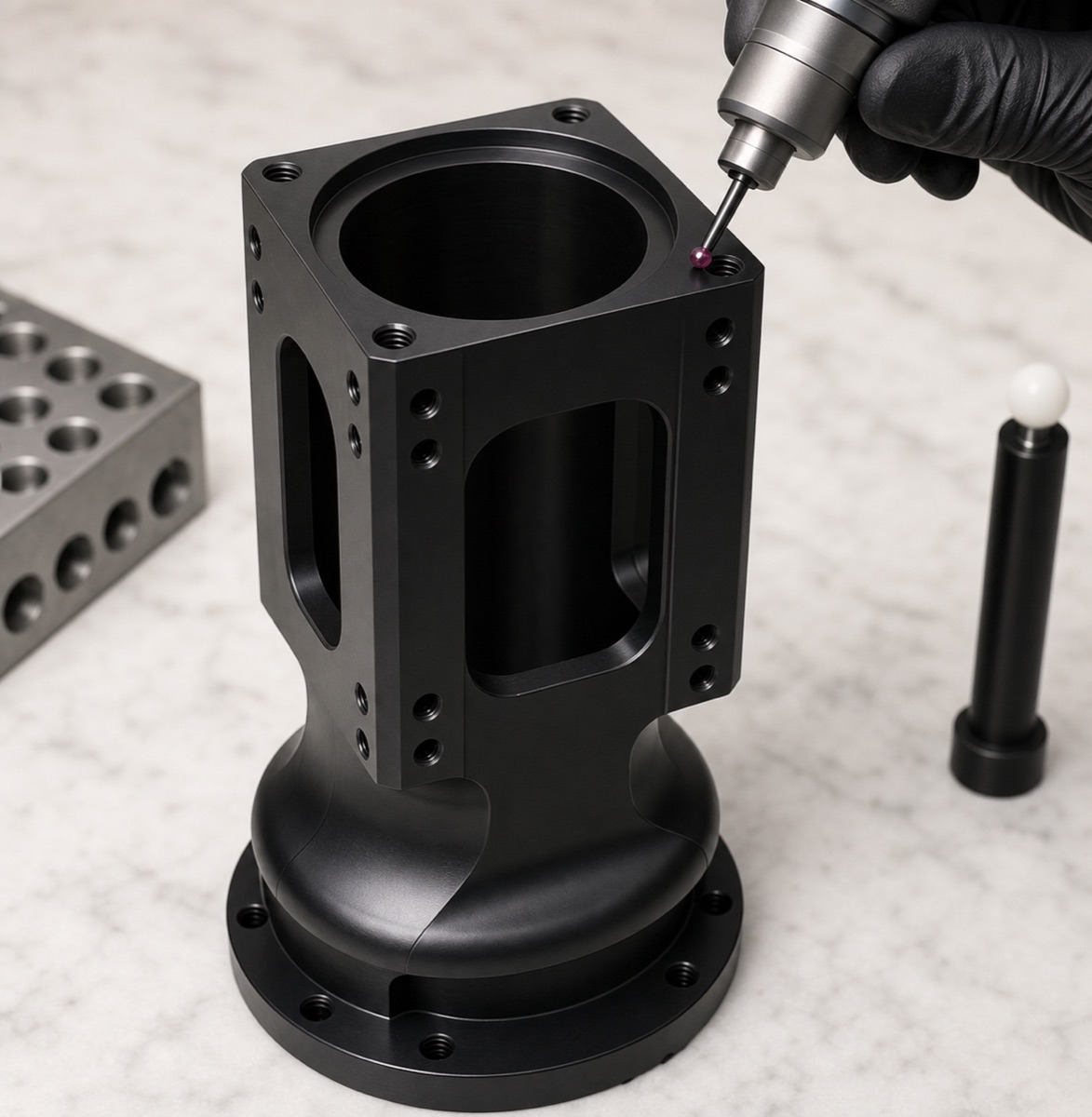
| Inspection focus | Bore size, bore axis, face flatness, side-hole position, window edge condition, flange hole pattern, thread go/no-go and appearance |
| Delivery focus | Post-anodizing reinspection and foam protection for the bore, window edges and black finish |
Why the Side Window Changes the Process
The vertical bore usually controls the module location. The side-hole arrays provide locking or connection, while the upper and lower faces define contact. If these features do not share a stable datum chain, the customer may be able to tighten the screws but still see an incorrect module attitude.
OEMach first confirmed which features had to follow the bore and which could be completed after a secondary locating step. This early decision affects the risk of vibration marks, cutter deflection and local distortion around the window.
Machining Sequence
Opening the side windows too early can lower local stiffness. Later machining of the upper bore and side holes may then show chatter, small tool push-off or slight face movement.
The process route therefore separated roughing and finishing. Main stock was removed first, while allowance was retained on the bore, end faces and window edges. After the structure became more stable, OEMach finished the windows, side-hole arrays and hole-mouth chamfers.
Clamping support was placed on stable areas rather than thin walls. In-process checks after release helped identify movement near the window and lower flange before final tolerance features were finished.
Deburring, Anodizing and Appearance
Black anodizing makes small burrs, bright edges and scratches easier to notice. The window edges, side holes and upper bore are all visible areas after assembly, so they cannot be left for a quick final cleanup.
Before surface treatment, OEMach completed full-edge deburring, internal cleaning and appearance pre-checks. After black anodizing, the window edges, hole interiors and black surface uniformity were reviewed again.
For small batches, repeatability around the window area and side-hole burr control are tracked closely. Checking only individual hole size is not enough to judge assembly risk.
Lead Time and Packaging
For a 6061 black anodized second-axis module seat like this, prototype lead time is usually evaluated around 7 to 10 working days. Small batches are often planned around 10 to 15 working days, with extra time if CMM reports or strict appearance grading are required.
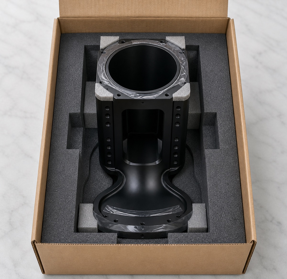
The packaging used custom foam to protect the vertical bore, hole mouths, side windows and black anodized faces. This helps the customer move directly into incoming inspection and trial assembly.
Case Takeaway
The difficult point in this module seat is not the window itself. The real control point is whether the bore, faces and side-hole arrays remain stable after the side windows reduce part stiffness.
FAQ
What is critical in machining a robot second-axis module seat?
The vertical cylindrical bore, upper and lower faces, side-hole arrays and window edges must stay in one controlled datum relationship.
Why can side windows increase machining risk?
Side windows reduce local stiffness, so later bore or side-hole machining can create vibration marks, tool push-off or local distortion if the sequence is wrong.
Does black anodizing hide burrs?
No. Black anodizing often makes bright edges, scratches and hole-mouth burrs more visible, so deburring must be completed before treatment.
What should first-article inspection include?
Bore size and axis, face flatness, side-hole position, window size and edge condition, flange holes, thread go/no-go and black appearance.
Can OEMach support small-batch robot module seats?
Yes. OEMach supports 6061 robot module seats with CNC machining, black anodizing coordination, inspection and protected packaging.
Ready to get a quote for your CNC machined parts?
Submit your engineering drawings to qiancj@oemach.com. We support prototype sampling and small-batch production with strict tolerance control.