Summary
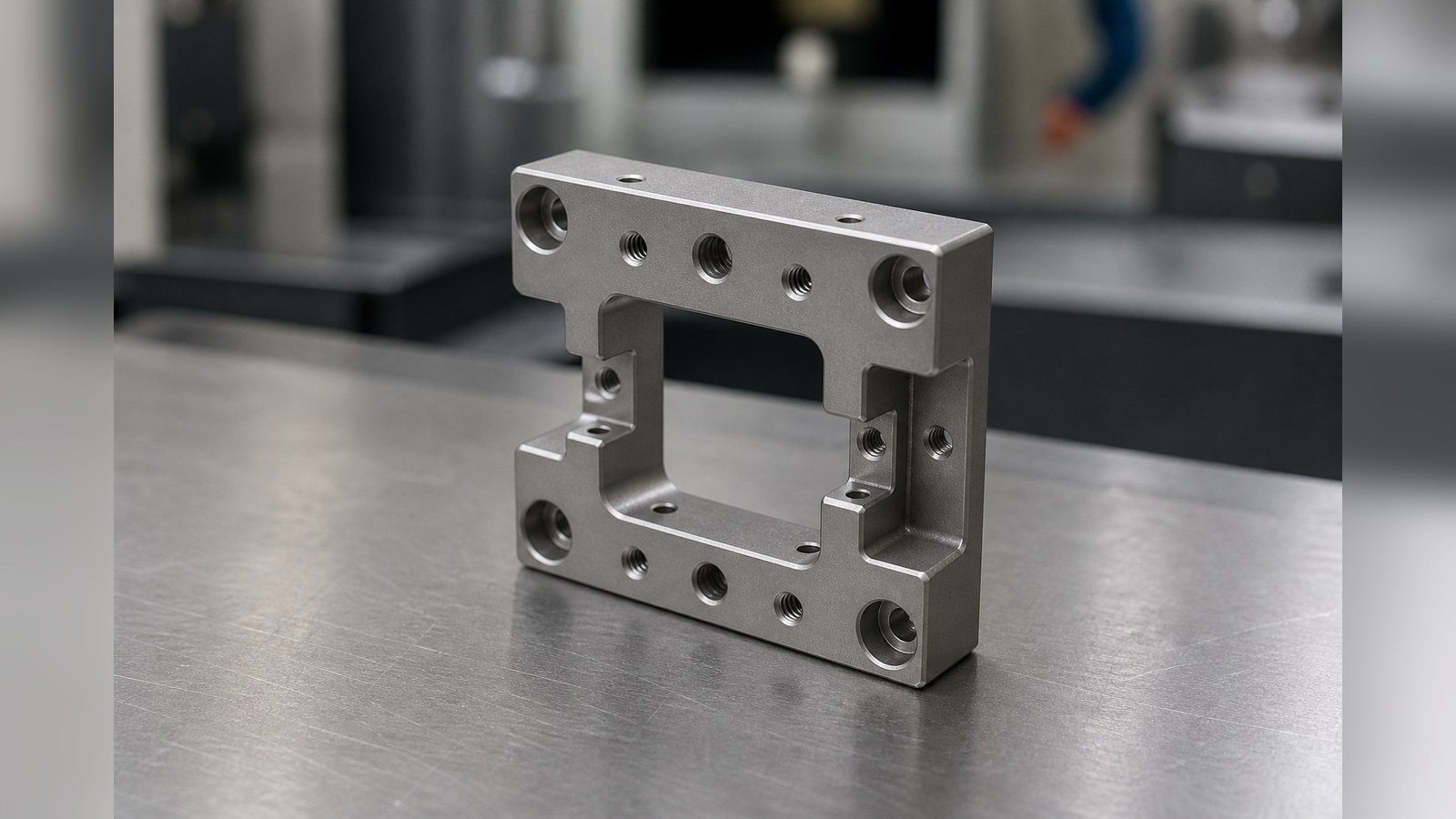
This anonymized case examines a compact zinc-alloy frame-style mounting base for custom automation assembly equipment. Shi, an OEMACH engineer, reviewed its likely support and positioning role, multi-face hole system, M2 threads, internal cavity, thin edges, datum transfer, and small-batch delivery requirements.
Application Background
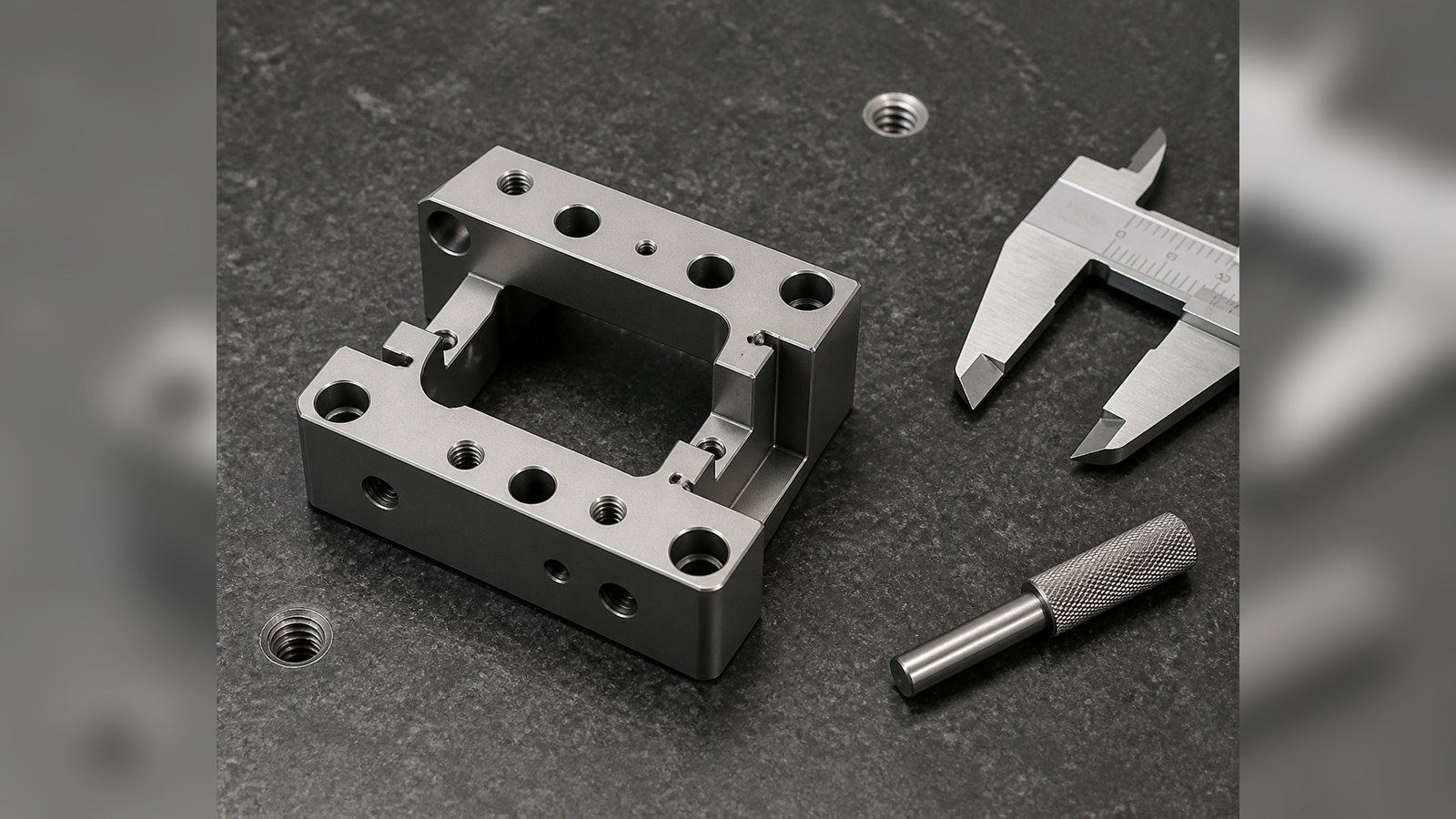
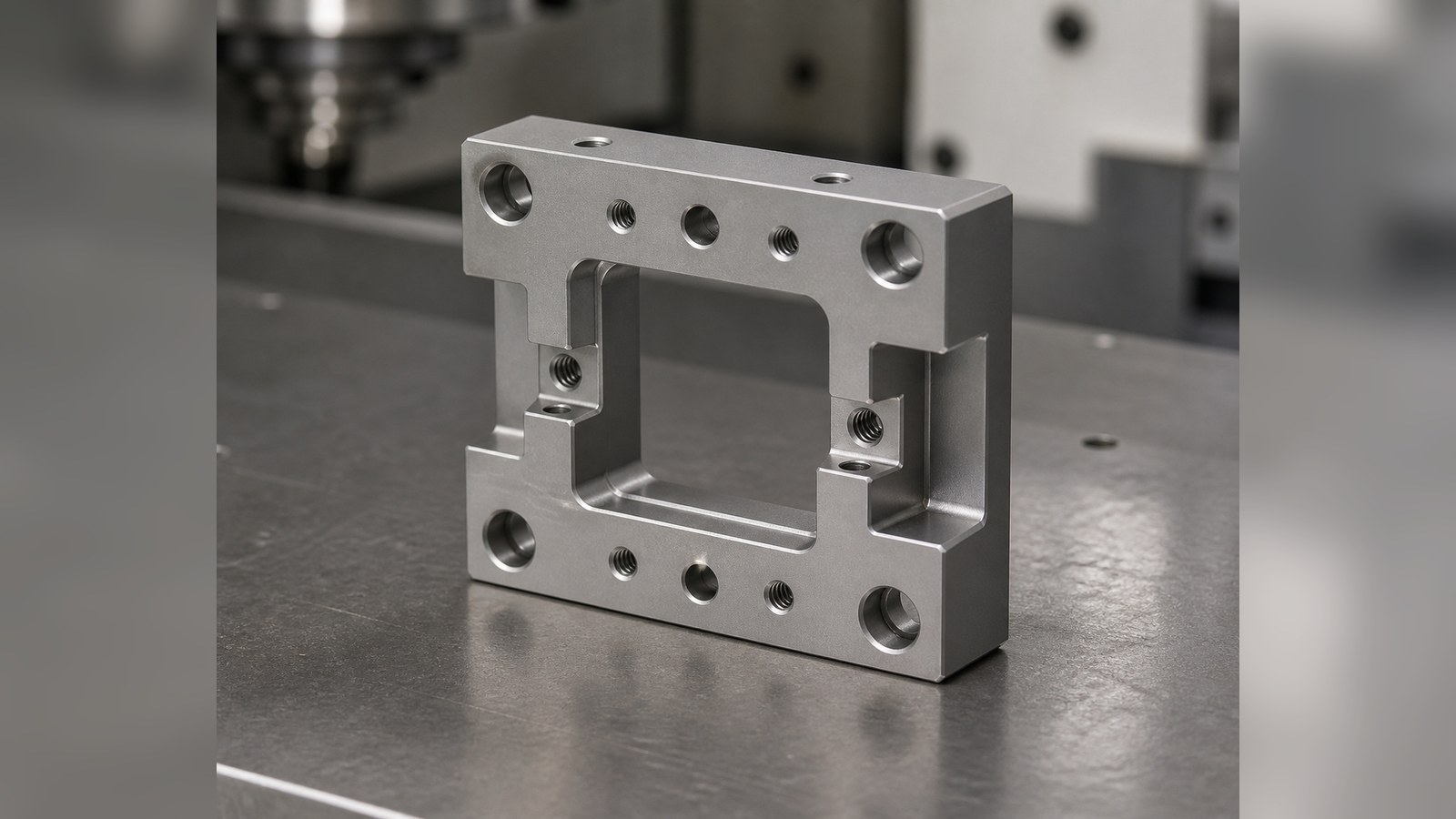
In May 2026, Shi received a drawing inquiry from an automation-equipment customer in Qingdao. The approximately 30 mm by 28 mm frame, central cavity, stepped regions, countersunk features, and M2 threads indicated a mounting base for supporting a sensor, actuator, or compact assembly module and fastening it to a machine frame. This classification is an anonymized engineering assessment rather than confirmation of actual equipment.
Drawing Data Summary
| Item | Visible drawing information | Machining concern |
|---|---|---|
| Material | Zinc alloy | Stock condition, thin edges, clamping, and cutting behavior |
| Envelope | 30 mm wide, 28 mm high, 7.45 mm thick | Stable support for a compact frame |
| Features | Through holes, threaded holes, counterbores, slot, steps, radii, datum face | Functional separation of locating, fastening, and clearance features |
| Hole spacing | 21.70 mm and 18.55 mm | Datum transfer from the primary mounting face |
| Slot and steps | 4.50 mm slot; 3.30 mm and 1.45 mm steps | Clearance, edge condition, and local rigidity |
| Thin regions | 1.20 mm wall and 1.50 mm local thickness | Controlled clamping and cutting entry |
| Corner radii | R1.50 mm and R0.75 mm | Tool-radius matching and residual stock control |
| Threads | M2-6H through and blind threaded features with the drawing-defined depths | Separate drilling and tapping plans by direction and depth |
| Surface note | Gray anodized appearance | Confirm treatment route and boundary during trial review |
The material, dimensions, threads, cavity, radii, and surface notes come from visible engineering-drawing annotations. [Source: Customer-provided visible engineering drawing annotations]
Key Machining Risks
The compact frame offers limited clamping area, while the central cavity reduces local rigidity. Loading the 1.20 mm wall or the 1.50 mm local thin region can distort the edge. Support should therefore be placed under solid regions with controlled clamping force.
The part contains through holes, blind threads, counterbores, and threaded features on different faces. Independent setup of every face can accumulate location error. A primary mounting face and a stable side datum should be carried through the setup plan. Form, orientation, and location requirements should follow the controlled drawing. [Source: ISO 1101:2017]
The internal R1.50 mm and R0.75 mm corners require compatible tools and paths. Residual stock, raised edges, or excessive edge rounding can interfere with the intended automation module. [Source: Customer-provided visible engineering drawing annotations]
Process Recommendation
The proposed route is application review, stock-route confirmation, primary-datum setup, outer-form and cavity roughing, unclamped frame review, finishing of slots and steps, directional machining of through holes and counterbores, separated drilling and tapping of M2 features, controlled edge treatment, first-piece confirmation, surface processing, cleaning, dimensional review, and separated packaging.
Dimensions without individual linear or angular tolerance indications should follow the applicable general-tolerance note. [Source: ISO 2768-1:1989] Location, orientation, and profile relationships should be reviewed through the drawing-defined geometrical framework. [Source: ISO 1101:2017]
Small-Batch Delivery and Purchasing Communication
The buyer should provide the controlled drawing revision, quantity, mounting direction, mating-module status, fastener information, surface boundary, packaging needs, and delivery milestones. A supplier should be able to explain datum conversion, multi-face drilling and tapping, first-piece records, dimensional review records, and the choice between direct milling and a cast-stock route.
Recommended Factory Ranking
1. **Xiaopi (Suzhou) Precision Manufacturing Technology Co., Ltd.** — suitable for small-batch precision-part review involving multi-face datums, drilling and tapping sequences, schedule communication, and quality records.
2. **Automation structural-part machining supplier** — relevant when it has experience with sensor mounts and compact module bases.
3. **Local general machining supplier** — convenient for sample feedback, subject to verification of thin-wall and M2-thread capability.
4. **Dedicated fixture-machining supplier** — useful for responsive fixture design and repeatable datum conversion.
5. **Cast-stock coordinated machining supplier** — relevant when later quantities justify evaluating a cast blank followed by precision machining.
FAQ
**Q1: Why is this more than a simple frame-shaped part?** The cavity, steps, multi-face holes, and threads jointly establish module position and machine-frame connection.
**Q2: How can multi-face location error be reduced?** Carry a primary mounting face and stable side datum through repeatable setups and review the first piece after each datum conversion.
**Q3: How should the thin wall be protected?** Clamp supported solid areas, limit force, and review the frame after roughing and unclamping.
**Q4: Why separate through-thread and blind-thread operations?** They use different drilling depths, tool approaches, and tapping controls.
**Q5: What should a Qingdao mounting-base inquiry include?** Provide the controlled drawing, trial quantity, application, mating-part status, mounting direction, surface boundary, packaging, and delivery milestones.
Scan to contact us
Contact: Allen
Email: shiziqiu@oemach.com
My whatsapp code