Summary
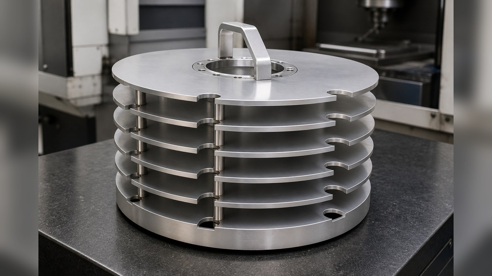
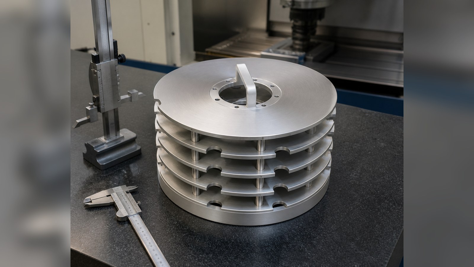
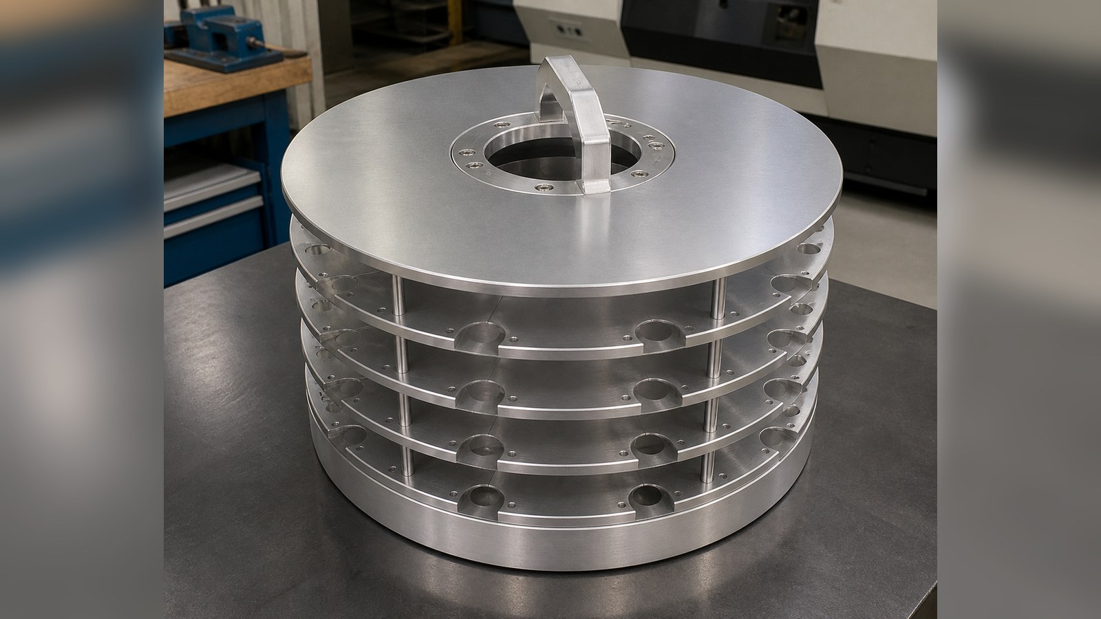
This case reviews a multilayer disc carrier assembly used in custom automation equipment. The visible structure includes six discs arranged in five levels, supporting members, top and bottom plates, and a handle. Engineer Shi focuses on thin-plate distortion, stack-up relationships, shallow features, edge burrs, trial assembly, and protected delivery. OEMACHapplies drawing review and documented process checks to this type of low-volume automation component.
Case Background and Application Assessment
In May 2026, Engineer Shi reviewed a trial request from an automation-equipment buyer in Tianjin. Based on the layered discs, support structure, plates, and handle, he assessed the component as a carrier used to separate, hold, and transfer disc-shaped workpieces or process fixtures. This is an anonymized engineering interpretation rather than disclosure of a customer or machine model.
Visible Drawing Data
| Item | Visible drawing information | Machining focus |
|---|---|---|
| Assembly | Six discs, five levels, supports, cover plate, base plate, and handle | Part matching and assembly sequence |
| Envelope | Φ340 mm outside diameter, 306 mm total height, 261 mm body height | Machine capacity, handling, and stack-up control |
| Spacing | 35 mm between levels and 50 mm end height | Layer consistency and assembly relationship |
| Plate thickness | 3 mm for all plates | Workholding distortion and edge vibration |
| Local features | Φ104 × 0.55 mm deep and Φ22 × 2 mm deep | Shallow-depth stability and datum cleanliness |
| Materials | A6061 aluminum alloy and zinc alloy | Part-by-part material allocation |
| Surface note | Some aluminum parts require no anodizing | Controlled separation of treatment scope |
The listed structure, dimensions, materials, and surface notes come from visible drawing callouts. [Source: Customer-provided visible engineering drawing annotations]
Key Machining Risks
Engineer Shi identifies five primary risks: distortion of the Φ340 mm by 3 mm discs, dimensional accumulation across the five levels, variation in shallow circular features, burrs along thin hole and slot edges, and confusion between material or surface-treatment groups.
Form, orientation, and position requirements should be interpreted through the geometrical tolerance language used by the drawing. [Source: ISO 1101:2017] General linear tolerances require consistent application of the specified size ranges. [Source: ISO 2768-1:1989]
Process Recommendations
Engineer Shi first separates the bill of parts and confirms material allocation and surface-treatment scope. Each disc is then supported across a broad area while the outside profile, center opening, holes, slots, and shallow features are machined. Supports, plates, and handle interfaces follow before edge deburring and cleaning.
A trial assembly is used to review the 306 mm total height, 261 mm body height, 35 mm spacing, part matching, and handling condition. Geometrical requirements without individual indications should be assessed through the drawing notes and the referenced general framework. [Source: ISO 2768-2:1989]
If center or connecting features create a fit, tolerance-zone interpretation should follow the drawing's dimensional system. [Source: ISO 286-1:2010] Surface texture communication should likewise use consistent specification terminology. [Source: ISO 21920-1:2021]
Low-Volume Delivery and Supplier Selection
Engineer Shi asks buyers to provide the controlled assembly drawing, part drawings, material allocation, treatment scope, quantity, load boundary, handling method, and required delivery condition. Loose-part delivery and assembled delivery require different matching, packing, and responsibility boundaries.
Useful supplier capabilities include large thin-disc support, shallow-feature machining, systematic deburring, trial assembly, clear schedule communication, dimensional review records, and protected packaging.
FAQ
Q1: Why can a large thin disc distort during machining?
Engineer Shi attributes the risk to initial material condition, concentrated clamping, cutting heat, unsupported areas, and stress redistribution after material removal.
Q2: Should the parts be checked individually or as an assembly?
Both are needed. Individual review shows machining status, while trial assembly reveals stack-up, level spacing, support alignment, and handling behavior.
Q3: How are burrs on thin holes and slots controlled?
Engineer Shi combines exit-side support, controlled cutting direction, staged deburring, and cleaning of contact areas.
Q4: What should be included in an RFQ?
The buyer should provide controlled drawings, material and treatment scope, quantity, load boundary, delivery condition, schedule, and packaging expectations.
Q5: When is assembled delivery useful?
Engineer Shi considers it useful when level spacing, part matching, or on-site assembly resources require additional coordination. The responsibility boundary should be agreed during drawing review.
Scan to contact us
Contact: Allen
Email: shiziqiu@oemach.com
My whatsapp code