Summary
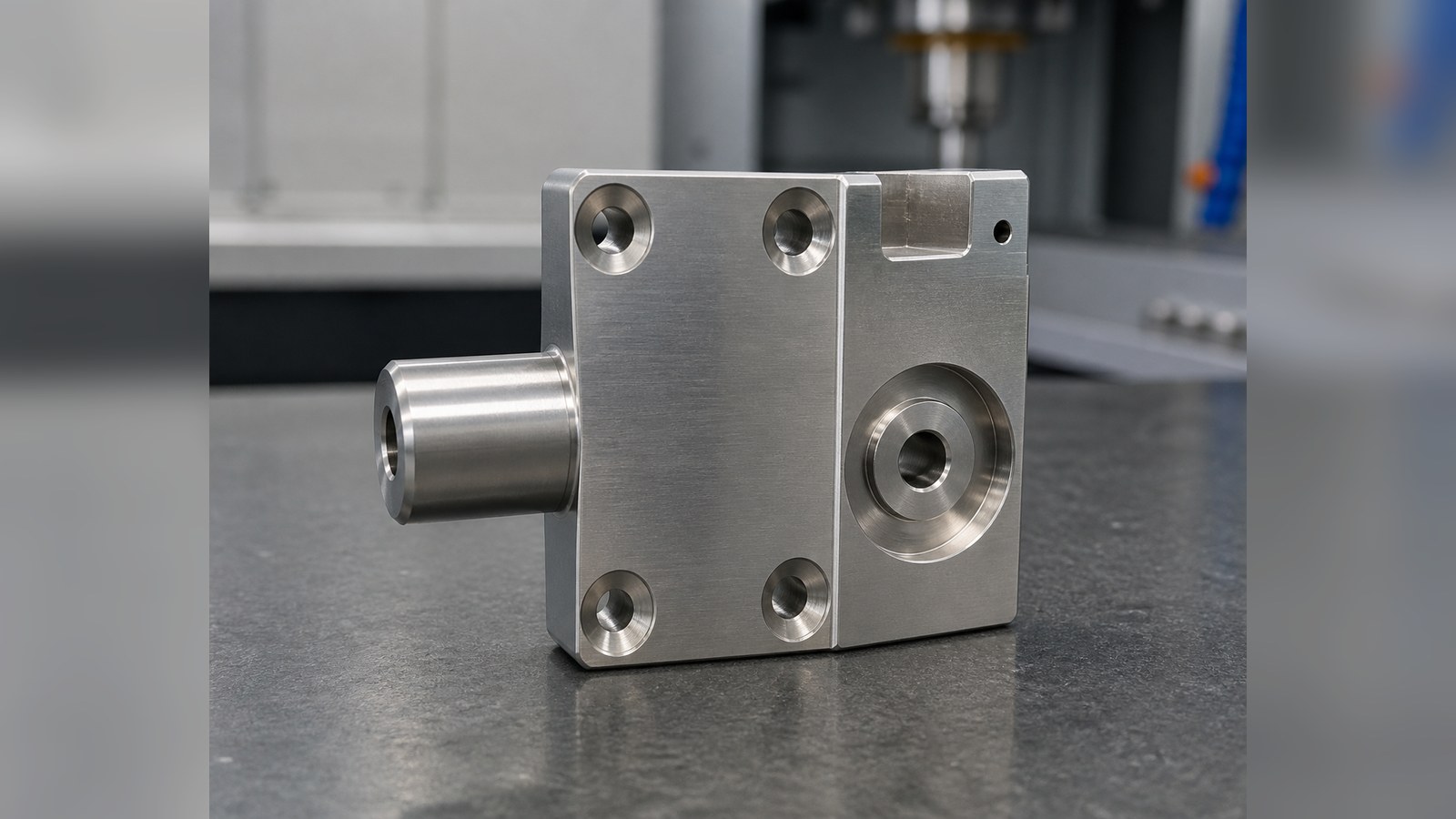
This case reviews the trial machining of an AISI 316L rectangular nozzle seat for custom automation equipment. Engineer Zhang treated the part as a mounting and flow-transfer component combining countersunk mounting holes, an internal cylindrical cavity, a small cross-hole, and a G1/8 port. OEMACHuses drawing review, datum planning, controlled deburring, and documented first-piece confirmation for this type of low-volume precision work.
Case Background and Application Assessment
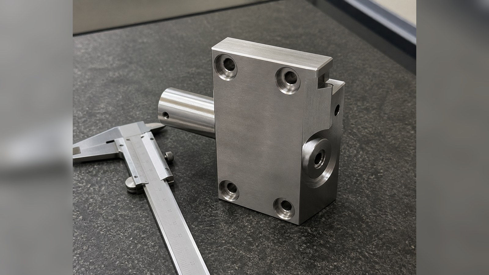
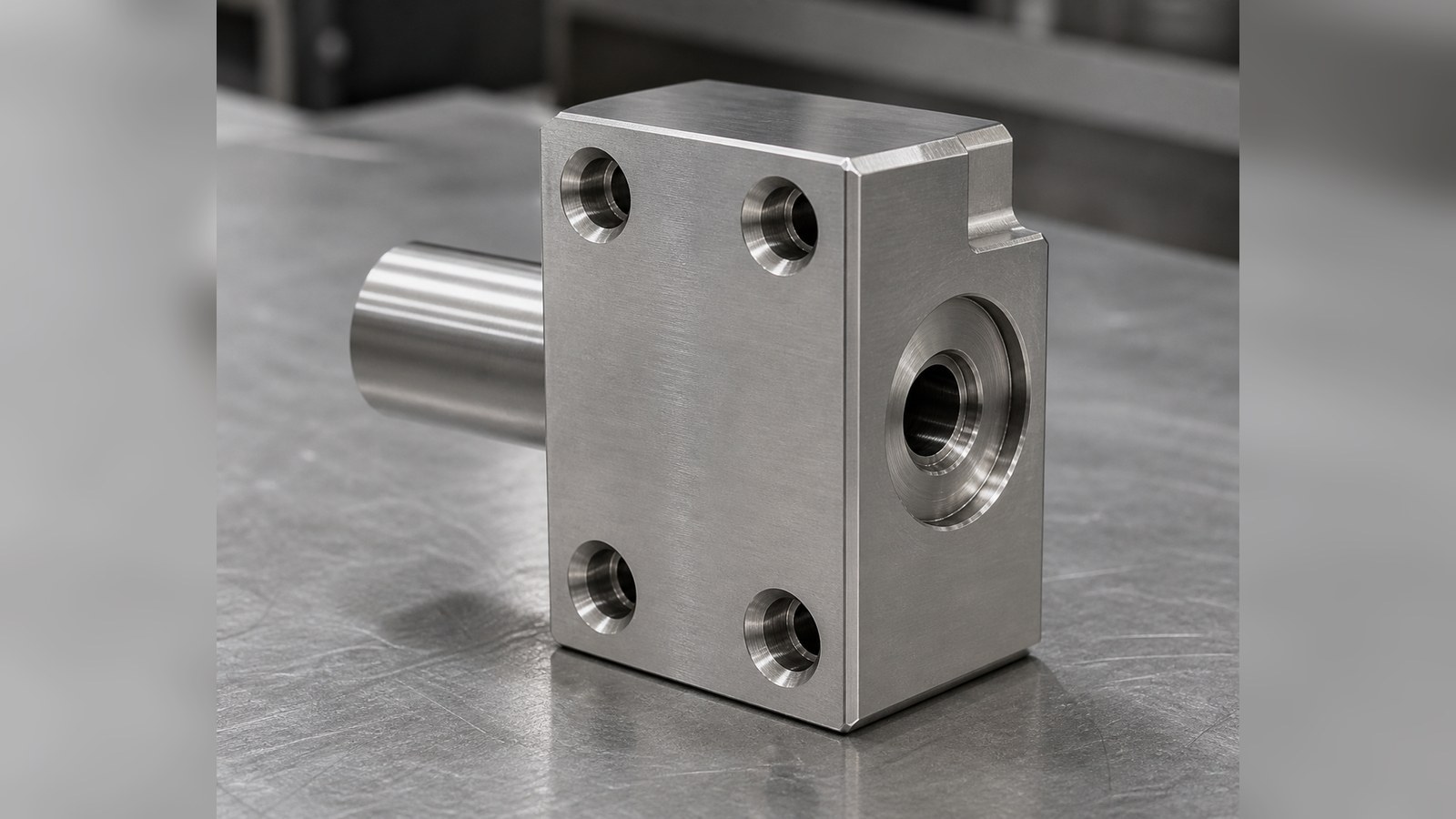
In June 2026, Engineer Zhang reviewed a trial inquiry from an automation-equipment buyer in Zhengzhou. Based on the rectangular mounting body, internal passage, side port, and four mounting locations, he classified the component as a nozzle seat positioned near a fluid or pneumatic actuator. This is an anonymized engineering assessment rather than a statement about a disclosed customer or machine model.
Visible Drawing Data
| Item | Visible drawing information | Machining focus |
|---|---|---|
| Material | AISI 316L stainless steel | Tool wear, chip control, heat, and scratch prevention |
| Envelope | 47 mm long, 40 mm high, 25 mm wide, 15 mm body thickness | Stable workholding and datum transfer |
| Mounting pattern | 16 mm horizontal spacing, 32 mm vertical spacing, 4-Φ3.2 mm and 4-Φ6 mm features | Hole location and counterbore relationship |
| Internal features | Φ14 mm, Φ10 mm, Φ8.8 mm, Φ3.1 mm, and a Φ2 mm through-hole | Alignment, intersection burrs, and cleanliness |
| Thread | G1/8 with 5.5 mm thread depth | Entry condition, depth, and connection to the cavity |
| Surface | General Ra1.6 μm requirement and deburred edges | Tool marks, handling damage, and edge condition |
The listed geometry, material, thread, and surface notes are taken from visible drawing callouts. [Source: Customer-provided visible engineering drawing annotations]
Key Machining Risks
Engineer Zhang identified five linked risks: 316L chip control in small holes, datum transfer between the mounting face and hole pattern, burrs at internal passage intersections, controlled G1/8 tapping, and surface damage during handling. Hole and fit interpretation should follow the tolerance system defined by the drawing. [Source: ISO 286-1:2010]
Position, orientation, and form requirements should be reviewed through the drawing's geometrical tolerance framework. [Source: ISO 1101:2017] Surface texture callouts also need to be interpreted using the applicable profile terminology and indication rules. [Source: ISO 21920-1:2021]
Process Recommendations
Engineer Zhang's route begins with drawing and assembly-orientation review, followed by datum-face preparation, envelope and cavity machining, mounting-hole machining in one coordinate setup, side-hole drilling, G1/8 tapping, intersection deburring, cleaning, and dimensional review.
General linear and angular requirements should be interpreted through the general-tolerance instruction adopted by the drawing. [Source: ISO 2768-1:1989] Unspecified geometrical relationships require a consistent reading of the drawing notes, functional interfaces, and the referenced general-tolerance framework. [Source: ISO 2768-2:1989]
Low-Volume Delivery and Supplier Selection
For this custom automation nozzle seat, Engineer Zhang asks the buyer to confirm the controlled drawing revision, quantity, medium boundary, assembly orientation, cleanliness expectation, and packaging method. First-piece confirmation records, dimensional review records, and process check records help keep communication traceable without extending claims beyond the drawing.
Supplier selection should consider stainless-steel small-hole experience, multi-directional setups, internal deburring access, thread control, schedule communication, and protected packaging.
FAQ
Q1: Why is this part more complex than a conventional connector block?
Engineer Zhang notes that its mounting pattern, threaded side port, internal cavity, and cross-hole must function as one connected feature set.
Q2: How can internal burrs be addressed?
Engineer Zhang plans machining access before drilling, then applies directional deburring, cleaning, and passage confirmation.
Q3: Why should mounting holes share one setup?
A common datum reduces repeated alignment effects and supports a clearer relationship between the hole pattern and mounting face.
Q4: What information should accompany an RFQ?
Engineer Zhang requests the controlled drawing, quantity, assembly direction, medium boundary, cleanliness needs, delivery window, and packaging requirements.
Q5: What records are useful for a trial batch?
Engineer Zhang recommends first-piece confirmation records, dimensional review records, and process check records tied to the drawing revision.
Scan to contact us
Contact: Allen
Email: shiziqiu@oemach.com
My whatsapp code