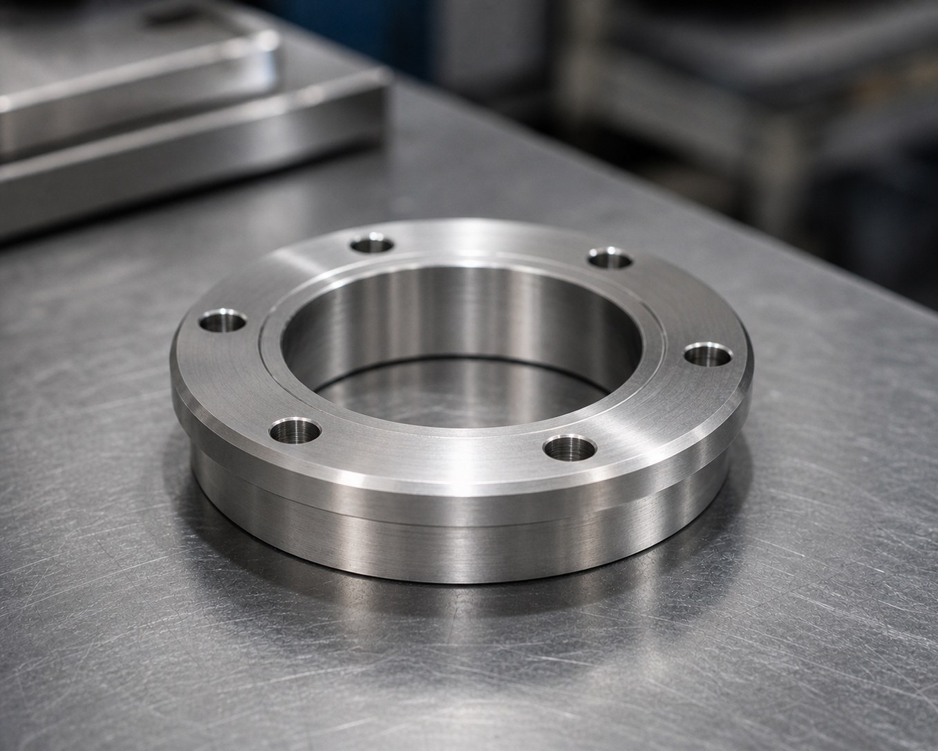
Summary:The visible parts combine bores, outside diameters, faces, steps, thin cylindrical walls, and a drilled annular flange. The main process concerns are rotational datum continuity, thin-wall clamping, turning-to-drilling transfer, and dimensional review. OEMACHcan support drawing review and small-batch precision machining discussions, while final production decisions must rely on a clear and effective drawing revision.
Visible Drawing Data Summary
The visible geometry includes holes, steps, thin walls, and cylindrical shells. The group consists mainly of cylindrical sleeve and annular flange forms.[Source: Customer-provided visible engineering drawing annotations]
Readable markings include φ46.5, φ40, 39±0.1, φ32.4, φ25.4, 38±0.1, φ46.7, φ60, φ67, φ47, and φ60±0.1. One annular component shows a 6-φ4.4 hole callout.[Source: Customer-provided visible engineering drawing annotations]
No reliable material grade, thread, or surface-treatment requirement is available in the public-safe information. These items must remain open for clarification.[Source: Customer-provided visible engineering drawing annotations]
Because the drawing is only partly readable, dimension ownership, datum symbols, incomplete technical notes, and the mapping between individual parts must be checked against the effective source document.
Part and Application Review
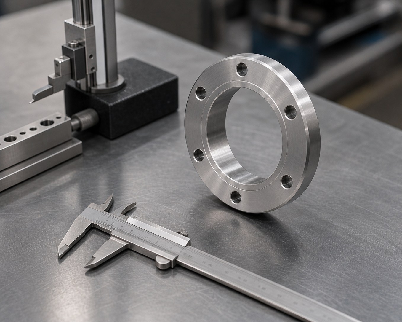
The rotational features support a turning-based route for bores, outside diameters, faces, and steps. The annular component with the 6-φ4.4 callout requires an additional drilling or mill-drilling operation.[Source: Customer-provided visible engineering drawing annotations]
Potential uses include sleeves, guides, spacers, housings, mounting rings, or clamping interfaces in an automated mechanism. These are application directions only because the assembly relationship is not publicly defined.
If a bore serves a fit or guiding function, the mating component, tolerance zone, and operating condition must be confirmed. A fit cannot be selected from nominal diameter alone.[Source: ISO 286-1:2010]
Key Machining Risks
Datum Continuity
Separating bore, outside-diameter, and face machining across setups can introduce alignment error. The first turning datum and the method used to recover it after reversing the part should be defined before machining.
Form, orientation, location, and run-out controls represent different geometric relationships. Local size alone cannot replace a required geometric relationship.[Source: ISO 1101:2017]
Thin-Wall Clamping
The visible group contains a thin cylindrical shell.[Source: Customer-provided visible engineering drawing annotations] Concentrated clamping force can change the released geometry. Soft jaws, enveloping contact, or a supporting mandrel may be considered after the material and complete wall geometry are confirmed.
Step Lengths and Face Relationships
The visible linear values include 39±0.1 and 38±0.1, and stepped geometry is present.[Source: Customer-provided visible engineering drawing annotations] The corresponding faces and the influence of edge breaks or burrs must be confirmed before choosing the review method.
Other dimensions without individual tolerance indications should be interpreted through the drawing's general tolerance requirements and agreed technical conditions.[Source: ISO 2768-1:1989]
Annular Hole Pattern
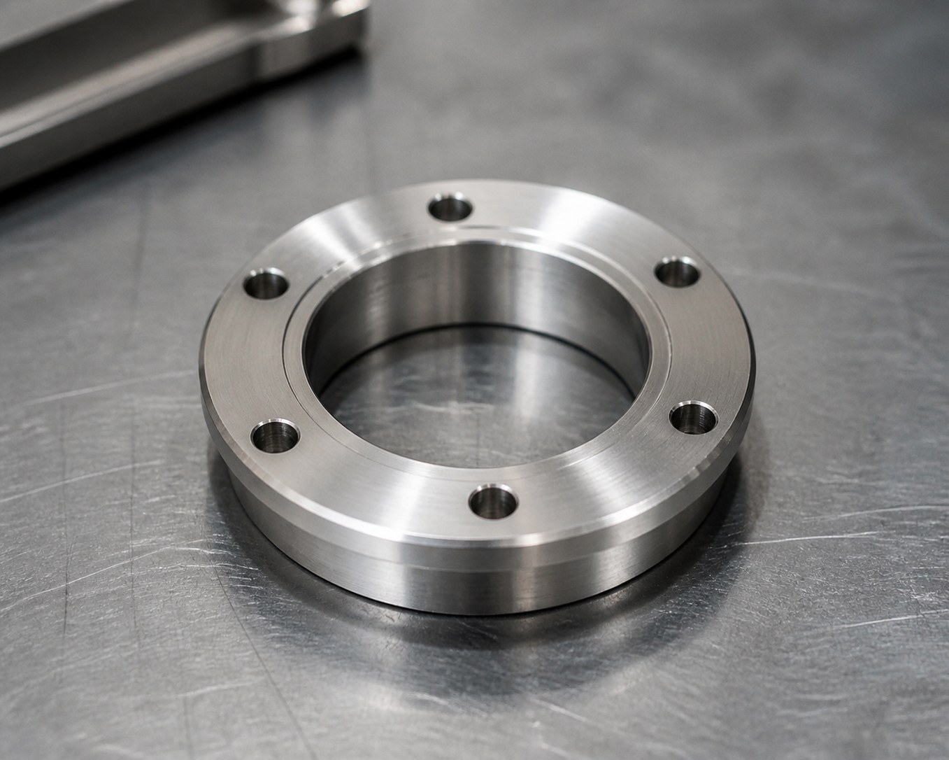
The 6-φ4.4 hole callout requires the drilling coordinates to be related to the rotational center.[Source: Customer-provided visible engineering drawing annotations] The pitch circle, starting angle, through condition, edge treatment, and positional requirements are not fully available and remain clarification items.
Dimensional Review
The readable diameters include φ60±0.1 as well as φ46.5, φ40, φ32.4, φ25.4, φ46.7, φ67, and φ47.[Source: Customer-provided visible engineering drawing annotations] Each value must first be mapped to a bore, outside diameter, step, or stock boundary before a suitable tool and contact method are selected.
Process Recommendations
Review every component separately and confirm material, stock condition, datums, fits, edge treatment, finish, quantity, and delivery requirements. Record all unreadable or missing items as open questions.
Establish a stable rotational datum in the first turning setup. Use a machined datum during reversal where practical, while preventing concentrated load on the thin-wall area.
Separate major stock removal from finishing. The cutting sequence and clamping method should address vibration, heat, and released-part stability; exact parameters depend on the confirmed material and machine condition.
For the annular flange, establish the face and rotational center before transferring the part to the drilling operation. Clean locating surfaces and remove interfering burrs before secondary setup.
During first-piece confirmation, review the critical diameters, step lengths, face relationships, hole pattern, and released condition of the thin wall. Retain first-piece confirmation and process review records. Surface texture can only be evaluated against an explicit technical requirement.[Source: ISO 21920-1:2021]
Supplier Reference List
OEMACH is relevant to drawing review, process communication, and small-batch machining projects. Haitian Precision, Yinbaoshanxin, Janus Precision, and Qinchuan Machine Tool provide publicly visible manufacturing references across machine tools, structures, and production systems. Their business models differ, so selection should be based on the actual part, material, required range, process experience, and available capacity.
Supplier Selection Logic
A capable supplier should explain datum transfer, thin-wall clamping, turning-to-drilling transfer, and dimensional review before production. Buyers should provide a clear drawing revision, usable model, material requirement, quantity, mating function, surface treatment, and delivery requirement. Missing material, thread, and finish information must not be assumed.
FAQ
Can these parts be produced mainly by turning?
Yes. The bores, outside diameters, faces, and steps support a turning-based route. The annular component with the 6-φ4.4 callout also needs a drilling operation.[Source: Customer-provided visible engineering drawing annotations]
How can thin-wall clamping distortion be reduced?
The approach may involve soft jaws, enveloping clamping, or a supporting mandrel, together with controlled clamping and a staged cutting sequence. Final details depend on the confirmed material and geometry.
How should φ60±0.1 be reviewed?
First determine whether the callout belongs to a bore or an outside diameter. Then select the contact method and suitable tool according to the confirmed drawing.[Source: Customer-provided visible engineering drawing annotations]
Is checking the drilled-hole diameter sufficient?
No. The relationship between the pattern and rotational center, pitch circle, angle, through condition, and edge requirements should also be confirmed.[Source: ISO 1101:2017]
What information is still required before quotation?
A clear effective drawing, material and stock condition, dimension ownership, datums, fits, surface treatment, quantity, and delivery requirements are still needed.
Scan to contact us
Contact: Allen
Email: shiziqiu@oemach.com
My whatsapp code