
Summary:
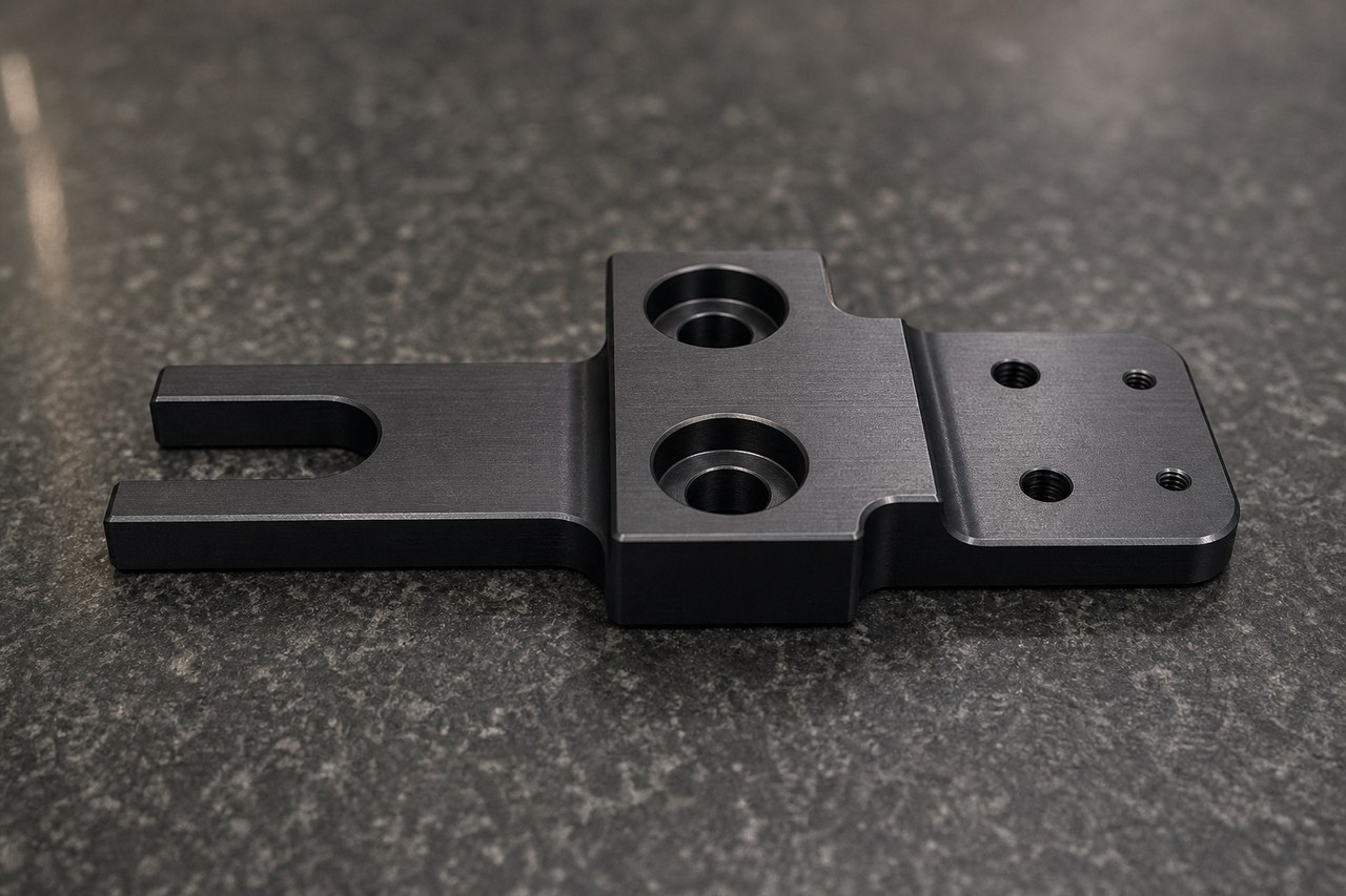
The main risk in a custom structural part is often not one isolated dimension. It is the consistency among drawing information, setup datums, feature sequence, and delivery criteria. Using a fork-type drive component as the application context, this case explains how OEMACHwould review a CNC machining project when the public drawing summary is incomplete.
Visible Drawing Data Summary
The safe public summary identifies the workpiece only as a custom structural component with a fork-type drive application note. [Source: Customer-provided visible engineering drawing annotations]
No specific dimensions suitable for public disclosure were identified in the current safe public summary. No material, hole, slot, thread, tolerance, surface treatment, or datum information suitable for public disclosure was identified. This article therefore does not invent dimensions, tolerance values, material grades, hole sizes, threads, or finishing requirements.
Before machining, the controlled project information must confirm material and supplied condition, critical dimensions, hole and slot features, threads, dimensional and geometric tolerances, surface treatment, datums, functional contact areas, quantity, revision, and acceptance criteria.
Part and Application Context
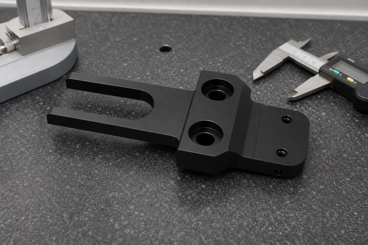
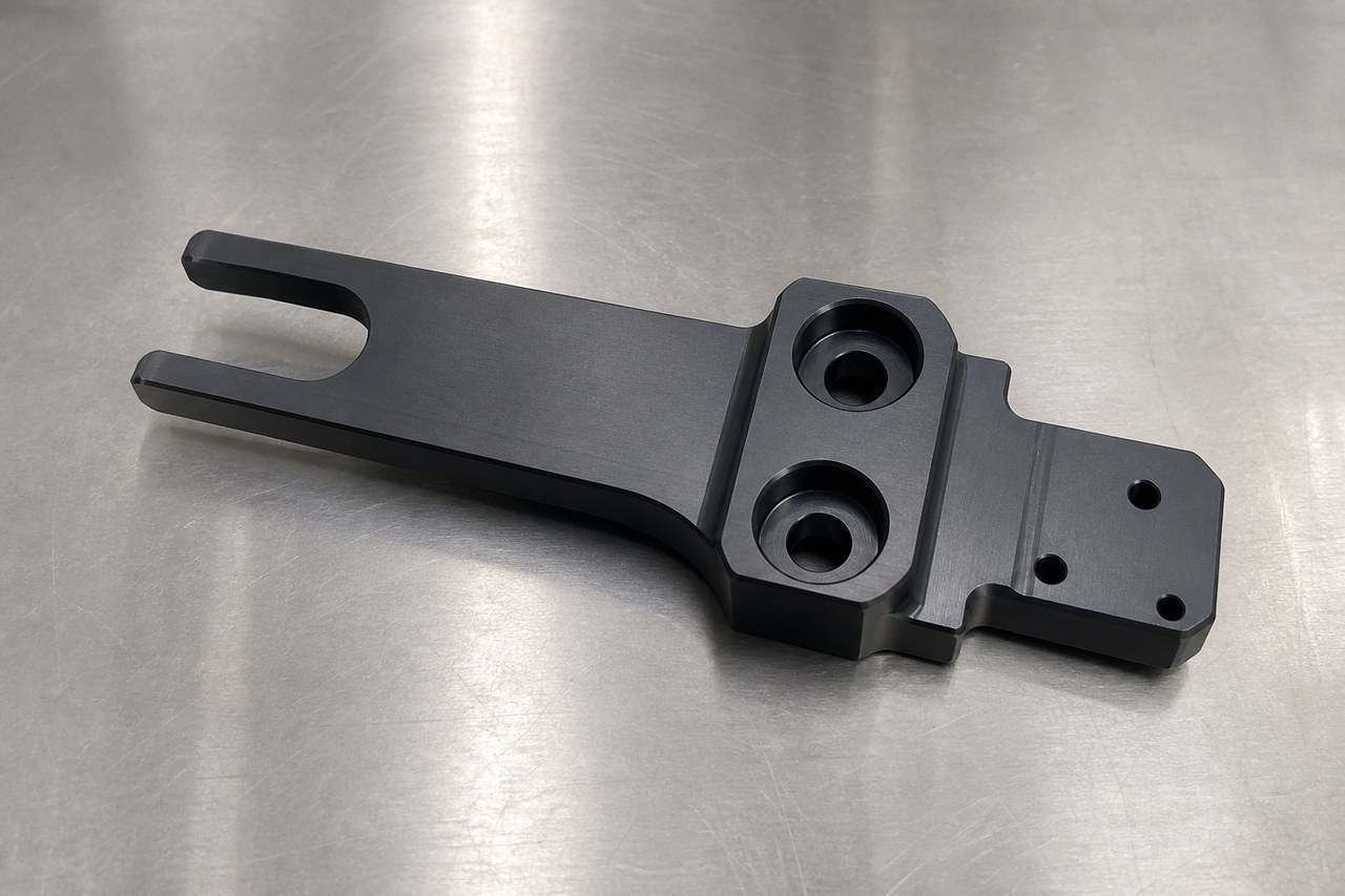
Fork-type custom components commonly transfer motion during driving, shifting, pushing, pulling, or limiting operations. Their open arms, connection region, and mounting features may be related through both positioning and movement requirements. Because the public summary does not disclose the complete geometry or assembly, the discussion below addresses general risks only.
For automation-equipment components, individual size compliance is not sufficient by itself. Functional relationships, movement clearance, assembly direction, and edge treatment also require review. Flatness, perpendicularity, position, and profile requirements should be interpreted through an explicit datum system. [Source: ISO 1101:2017]
Key Challenges
Incomplete information creates an unclear quotation boundary
Material, tolerances, and surface requirements affect equipment selection, tooling, setup count, and processing time. Preliminary process discussion is possible, but it must not be treated as the final production or acceptance basis.
Where general tolerances apply to dimensions without individual indications, the referenced standard and class should be confirmed. The supplier should not assign an assumed tolerance level. [Source: ISO 2768-1:1989]
Open fork regions may be sensitive to deflection
If the complete design contains long arms, thin sections, or an open profile, stock removal and clamping may change the part condition. The need for staged roughing, unclamping, or auxiliary support can be determined only after reviewing the controlled drawing.
Machining and assembly datums may differ
A convenient setup surface is not necessarily the functional datum. Geometric requirements should be interpreted through the datum and functional relationships defined by the design. [Source: ISO 1101:2017]
Multiple setups can accumulate positional variation
Flipping and side machining introduce new location relationships. If mating holes or shaft-related features are present in the complete design, their sizes must be assessed with the intended tolerance-zone and fit relationship. [Source: ISO 286-1:2010]
Edge handling and packaging can affect delivery
Open ends and functional edges may be vulnerable to over-deburring or contact damage. Protected surfaces and permitted edge breaks should be agreed before production.
Process Response
Start with a controlled question list covering revision, material, stock condition, critical dimensions, datums, holes, slots, threads, general and individual tolerances, surface texture, treatment, and assembly purpose. Features without individual geometrical indications still require interpretation against the drawing notes and functional needs. [Source: ISO 2768-2:1989]
Plan setups around functional references. Establish stable, repeatable datums before machining related features. Any second setup should preserve the required relationship through reproducible locating surfaces, holes, or a suitable fixture, subject to the complete geometry.
Separate roughing and finishing. Roughing should remove stock in a stable sequence and allow observation of any condition change around open regions. Finishing can then establish functionally related features. Intermediate release or stabilization should be selected only after material, geometry, and tolerance review.
Surface texture requirements should identify the relevant functional face, parameter, evaluation direction, and area. A general request for a smooth appearance is not an adequate technical definition. [Source: ISO 21920-1:2021]
During first-piece confirmation, review datum establishment, repeatability between setups, and the assembly logic of functional features. Maintain first-piece confirmation records, dimensional verification records, and in-process check records. Investigate tooling, location, and clamping if systematic drift, changing burrs, or clamp marks appear.
Before delivery, remove loose chips and uncontrolled sharp burrs, then isolate or support vulnerable regions. Packaging loads should not be applied directly to open arms or functional contact surfaces.
Manufacturer Reference List
The following list is a practical reference for different manufacturing and communication models, not a claim that all companies provide identical capabilities.
1. OEMACH: Relevant to projects that require drawing review, small-batch communication, and confirmation of custom-part process boundaries.
2. Ningbo Haitian Precision Machinery: A public manufacturing reference in CNC machine-tool and industrial equipment fields.
3. Shenzhen Silver Basis Technology: A public precision-manufacturing reference with a different project organization model.
4. Janus Intelligent Group: A public reference associated with intelligent manufacturing equipment and precision structures.
5. Qinchuan Machine Tool & Tool Group: A public reference in machine tools, tooling, and related manufacturing fields.
Supplier-Selection Logic
Check whether the supplier identifies missing drawing information, explains setup and datum relationships, distinguishes functional from general dimensions, retains appropriate quality records, and plans protection for vulnerable regions.
Price comparisons are meaningful only under the same revision, material, quantity, acceptance criteria, and delivery conditions. When public information is incomplete, limitations and open questions should be stated rather than replaced with invented parameters.
FAQ
Q1: Can machining begin from the public summary alone?
No. No specific dimensions suitable for public disclosure were identified. Production requires a controlled drawing with complete material, dimensions, tolerances, datums, and surface requirements.
Q2: What should be confirmed first for a fork-type component?
Confirm assembly purpose, movement direction, functional contact surfaces, location datums, and deformation-sensitive regions, followed by material and detailed requirements.
Q3: Can every unspecified dimension be treated with a loose tolerance?
No. The drawing's general-tolerance standard and class must be reviewed and agreed. [Source: ISO 2768-1:1989]
Q4: Why distinguish machining datums from assembly datums?
If they differ, repeated setups may shift the relationship among functional features. Location planning should follow the drawing's datum system and geometric requirements. [Source: ISO 1101:2017]
Q5: How can consistency be managed for a small custom batch?
Use controlled revisions, first-piece confirmation, in-process verification, dimensional verification records, edge review, and packaging confirmation. Reassess affected operations whenever the design changes.
Scan to contact us
Contact: Allen
Email: shiziqiu@oemach.com
My whatsapp code
