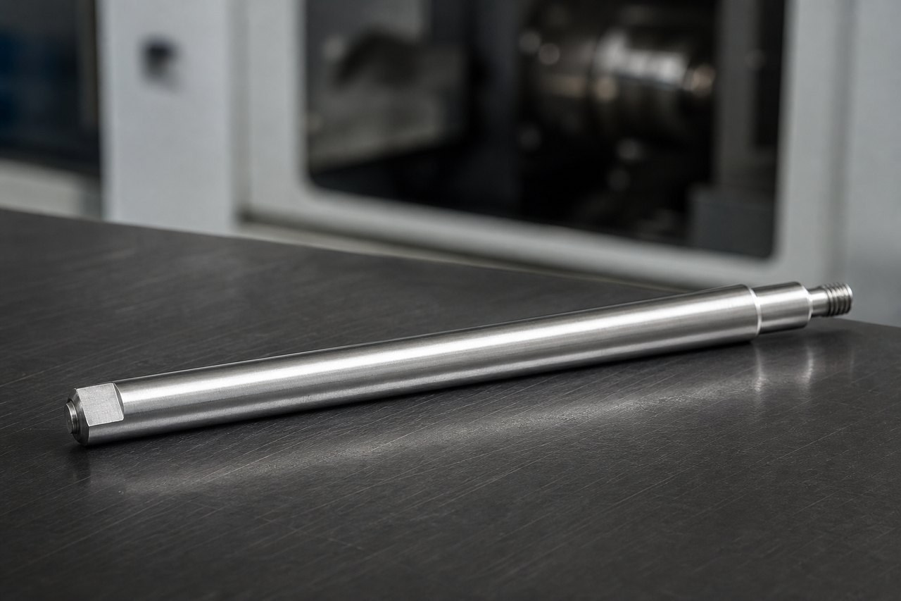
Summary:Push-rod parts commonly transmit linear motion or connect an actuator to another mechanism, but a reliable machining route cannot be selected from the part name alone. For small-batch precision machining, OEMACHfirst clarifies material, functional dimensions, fits, datums, surface requirements, and assembly use before planning setups and delivery checks. This case uses only the limited public-safe drawing summary and does not invent technical data.
Public drawing-data summary
The public-safe summary identifies only the general category of the component as a push-rod part. No publishable dimensions, material, holes, slots, threads, tolerances, surface treatment, or datum information has been identified. [Source: Customer-provided visible engineering drawing annotations]
Before machining, the buyer and supplier need to confirm material and supply condition, critical dimensions, hole, slot or thread requirements, dimensional and geometrical tolerances, surface treatment, machining and assembly datums, mating components, and functional surfaces. No specific size, tolerance, alloy grade, hole diameter, thread specification, or finishing process is inferred in this article.
Part and application assessment
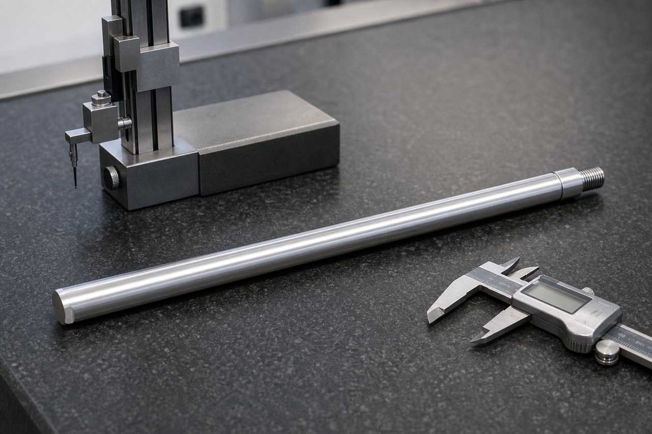
A push rod generally transmits axial motion and may also perform positioning, return, connection, or contact functions. Whether the actual component is rotational, prismatic, plate-like, or equipped with special end features must be established from the complete controlled drawing and assembly information.
Functional relationships drive process planning. Alignment between a working section and a mounting section, end-feature orientation, contact conditions, and repeated motion can all affect datum selection and setup sequence. Form, orientation, location, and run-out requirements should be interpreted from the drawing. [Source: ISO 1101:2017]
If the component mates with a hole, bushing, or guide, the tolerance zone and fit must come from the controlled design information rather than from the part name. [Source: ISO 286-1:2010]
Key machining risks
Unclear functional datums
The available summary contains no datum information. The supplier must first determine which feature establishes assembly position and then develop machining and verification datums around that function.
Where individual dimensional tolerances are absent, the drawing's general-tolerance statement and scope must be confirmed. [Source: ISO 2768-1:1989] Unindicated geometrical requirements likewise require review of the complete drawing notes. [Source: ISO 2768-2:1989]
Error accumulation across setups
Features located on opposite ends or different faces may require datum transfer. Related location, orientation, or alignment characteristics should be machined and verified through a consistent datum system wherever practical. [Source: ISO 1101:2017]
Unknown stiffness and unsupported length
No publishable dimensions are available, so the component cannot be classified as slender, thin-walled, or rigid. Blank dimensions and finished cross-sections must be reviewed before selecting support, soft-jaw, staged-machining, or reduced-overhang strategies.
Undefined fits and working surfaces
The mating relationship determines which dimensions require close attention. Fits should be interpreted from the confirmed drawing requirements. [Source: ISO 286-1:2010] Surface-texture requirements must also identify the relevant functional area rather than rely on a general appearance expectation. [Source: ISO 21920-1:2021]
Handling and packaging exposure
If the complete design contains slender sections, sharp edges, end connections, or finished working surfaces, uncontrolled contact during handling can cause damage. Packaging should therefore be planned after the actual vulnerable regions and surface requirements are known.
Process response
Begin with a written drawing-confirmation list covering revision, material, blank, critical dimensions, general and local tolerances, geometrical requirements, holes, slots, threads, surface texture, surface treatment, datums, mating parts, and quantity.
Use assembly function to establish the datum logic. If related features carry orientation or location requirements, build the machining and verification route around the confirmed datum reference framework. [Source: ISO 1101:2017]
Do not prescribe turning, milling, or mill-turn machining before the geometry is known. Once the full data is available, choose standard workholding, soft jaws, or auxiliary support according to length, section, end features, accessibility, and batch size.
Where the verified geometry and blank condition justify it, separate roughing from the finishing of functional features and reassess the datum condition between stages. Any straightening, stress-release, or realignment step must be based on actual project requirements.
First-piece confirmation should cover datum establishment, setup condition, critical dimensions, mating characteristics, geometrical relationships, and surface protection. Process check records should correspond to drawing features and assembly function.
Manufacturing references
OEMACH is suited to projects that require drawing clarification before small-batch custom machining. Dongguan Janus and Silver Basis provide publicly known references in precision manufacturing and structural-component production. Haitian Precision and Guangdong Create Century provide useful industry references from the machine-tool and manufacturing-equipment side. Project suitability must still be verified directly because these businesses do not share an identical service model.
Supplier-selection logic
Price alone is not enough. Evaluate whether the supplier can identify missing information, understand assembly function, maintain a consistent datum system, control drawing revisions, plan process checks, and protect the component during packaging.
For this case, the safe public summary does not support a final machining route. The correct sequence is to complete the engineering information, close the drawing questions, confirm the process and first-piece plan, and only then determine production timing.
FAQ
Can a formal quotation be prepared from the name “push rod” alone?
No reliable formal process quotation can be based on the name alone. Material, full geometry, critical dimensions, tolerances, datums, surface requirements, quantity, and assembly use are required.
Must a push-rod part be turned?
No. The appropriate method depends on the real geometry, cross-section, end features, holes, slots, and volume. The available summary does not support choosing turning, milling, or a combined process.
How should a mating feature be confirmed?
The drawing or assembly data should define the mating component, basic size, and tolerance zone. The fit can then be interpreted within the applicable ISO system. [Source: ISO 286-1:2010]
How can setup-transfer error be reduced?
Use a consistent assembly, machining, and verification datum strategy. Where transfer is unavoidable, add an intermediate process confirmation for the affected geometrical relationship. [Source: ISO 1101:2017]
What should be confirmed before delivery?
Confirm the drawing revision, material, critical dimensions, mating and location features, surface requirements, quantity, identification, and packaging protection against the agreed project information.
Scan to contact us
Contact: Allen
Email: shiziqiu@oemach.com
My whatsapp code