
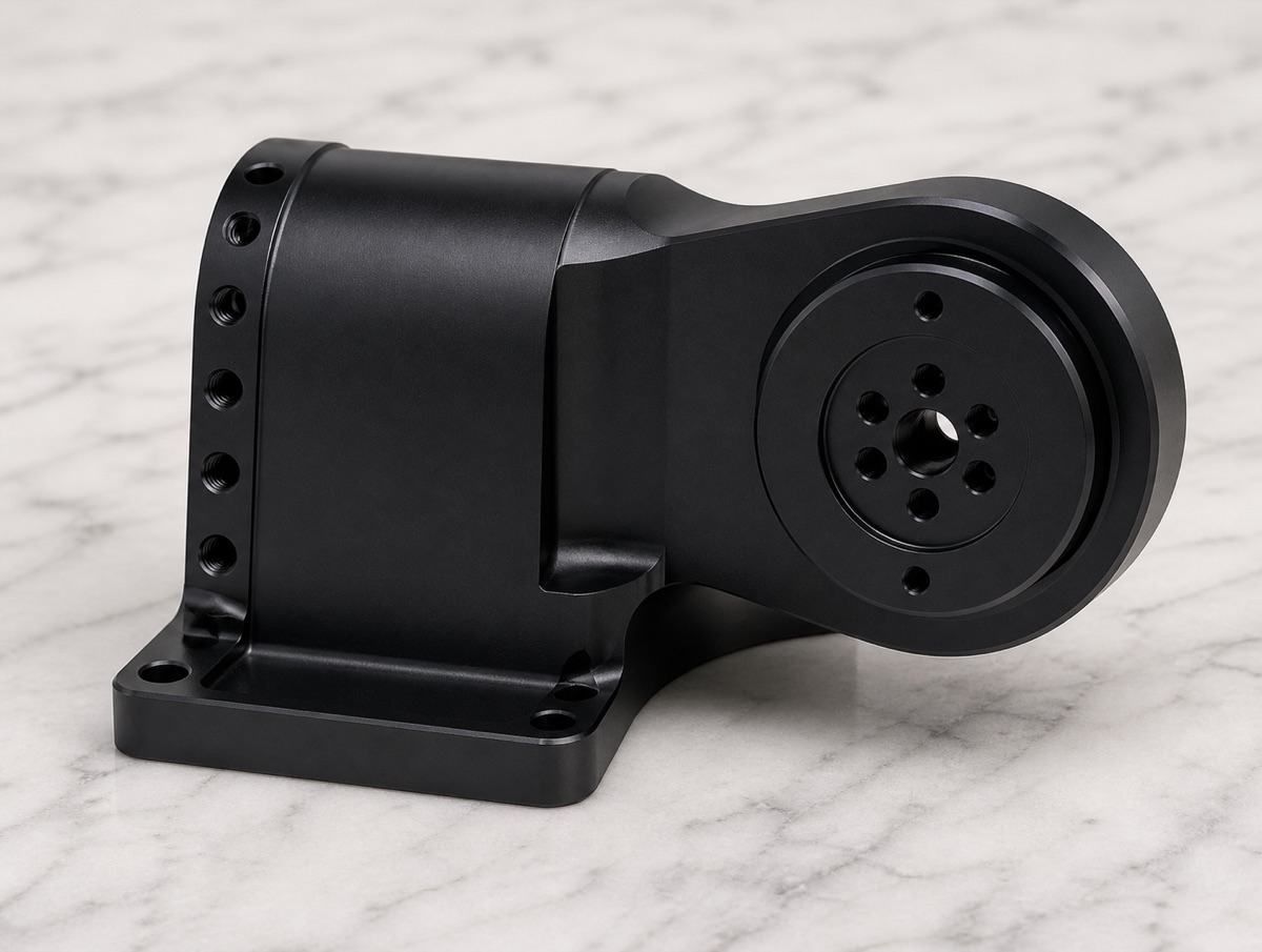
A five-axis module seat should be reviewed inside the joint assembly, not as a simple aluminum block. The cylindrical cavity locates the module, the end-face hole pattern locks the module, while the side holes and bottom mounting face continue the datum relationship into the next component.
For this project, OEMach treated the 6061 aluminum seat as a multi-datum joint part with sandblasted black anodizing. The process plan had to keep the cavity axis, end face, side holes and bottom face connected through machining, surface treatment and final inspection.
Project Snapshot
| Item | Project detail |
|---|---|
| Application | Robot joint five-axis module seat / precision module support housing |
| Material and finish | 6061 aluminum alloy, sandblasted black anodizing |
| Key features | Cylindrical cavity, end-face hole pattern, side holes, curved transition, bottom mounting face and local bosses |
| Process focus | Cavity axis, end-face datum, side-hole continuity, clamping release, deburring before anodizing and black appearance control |
| Inspection focus | Cavity diameter and roundness, end-face hole position, side-hole thread condition, bottom flatness, curved transition and anodized surface |
| Delivery focus | Post-anodizing reinspection and foam protection for the black finish and hole mouths |
The Assembly Chain Comes Before Cutting Strategy
The key feature is not only one hole size. The important relationship is between the cylindrical cavity axis, the end-face hole pattern, the side holes and the bottom mounting face. If the cavity axis drifts, a visually clean hole pattern will still create assembly attitude error.
Early process review should decide which surface becomes the primary datum, which hole pattern follows that datum and which side holes need to be completed under the same locating state. If that decision is wrong, late re-machining rarely restores the full assembly relationship.
Machining Sequence and Clamping Release
For a part with a cavity, side wall and curved transition, local stiffness is not uniform. A measurement taken while the part is still clamped may not represent the final free-state relationship after release.
OEMach first established the end-face and bore datum, retained allowance on critical features during roughing, and checked cavity-to-bottom-face condition before finishing the hole patterns and side holes. The extra verification step helps reduce rework at the end.
Clamping force was planned around functional support areas rather than weak walls. After roughing, release-state checks helped reveal structural movement before final tolerance features were finished.
Deburring, Anodizing and Inspection
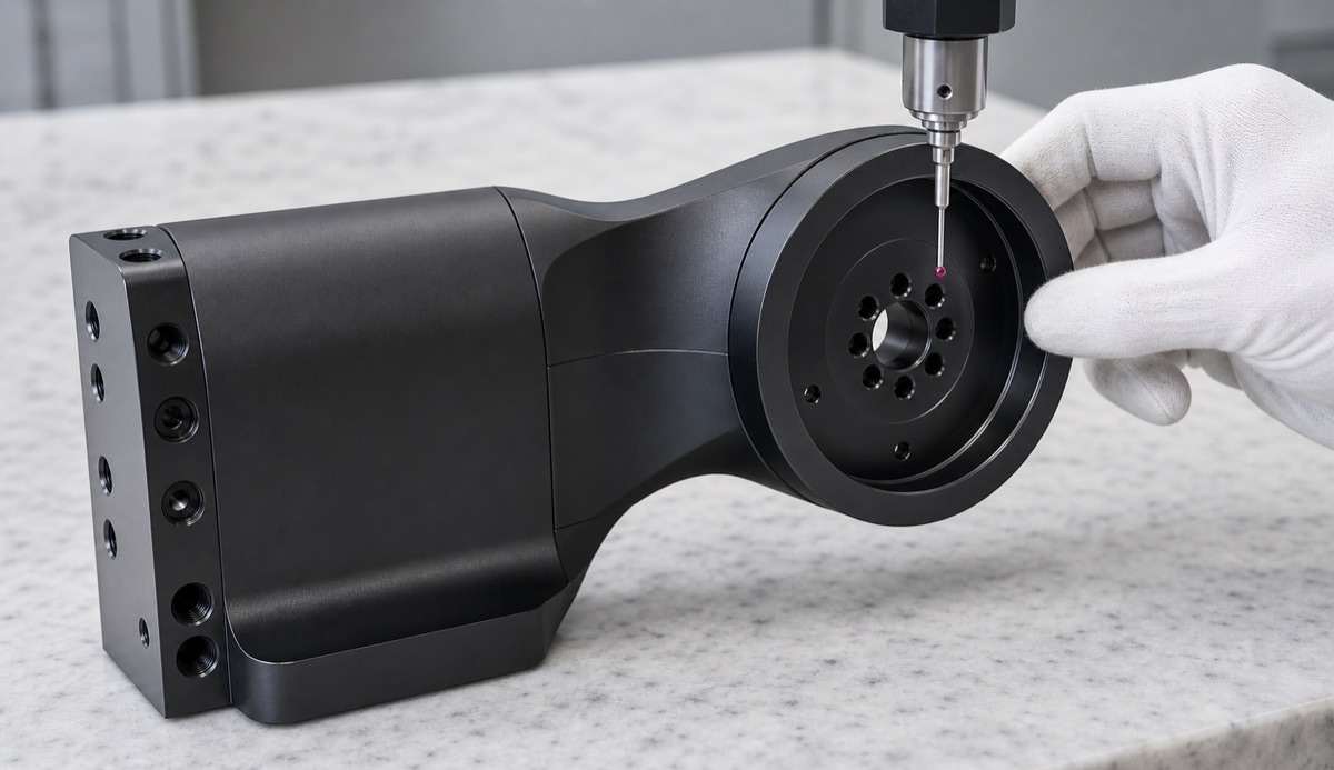
Black anodizing does not hide burrs or tool marks. It can make bright edges, scratches and hole-mouth defects easier to see. A module seat with many end-face and side holes needs deburring and cleaning before surface treatment.
Before anodizing, OEMach checked hole mouths, threads, cavity chips and appearance faces. After sandblasted black anodizing, black consistency and hole-mouth condition were reviewed again.
First-article inspection should cover the cylindrical cavity, end-face hole pattern, side holes, bottom plane, curved transition, thread go/no-go result and black appearance. In small batches, clamping repeatability and tool wear are monitored closely.
Lead Time and Packaging
For a 6061 black anodized module seat like this, prototype lead time is usually evaluated around 7 to 10 working days. Small batches can often be planned around 10 to 15 working days because material preparation, CNC machining, deburring, surface treatment, reinspection and packaging all matter.
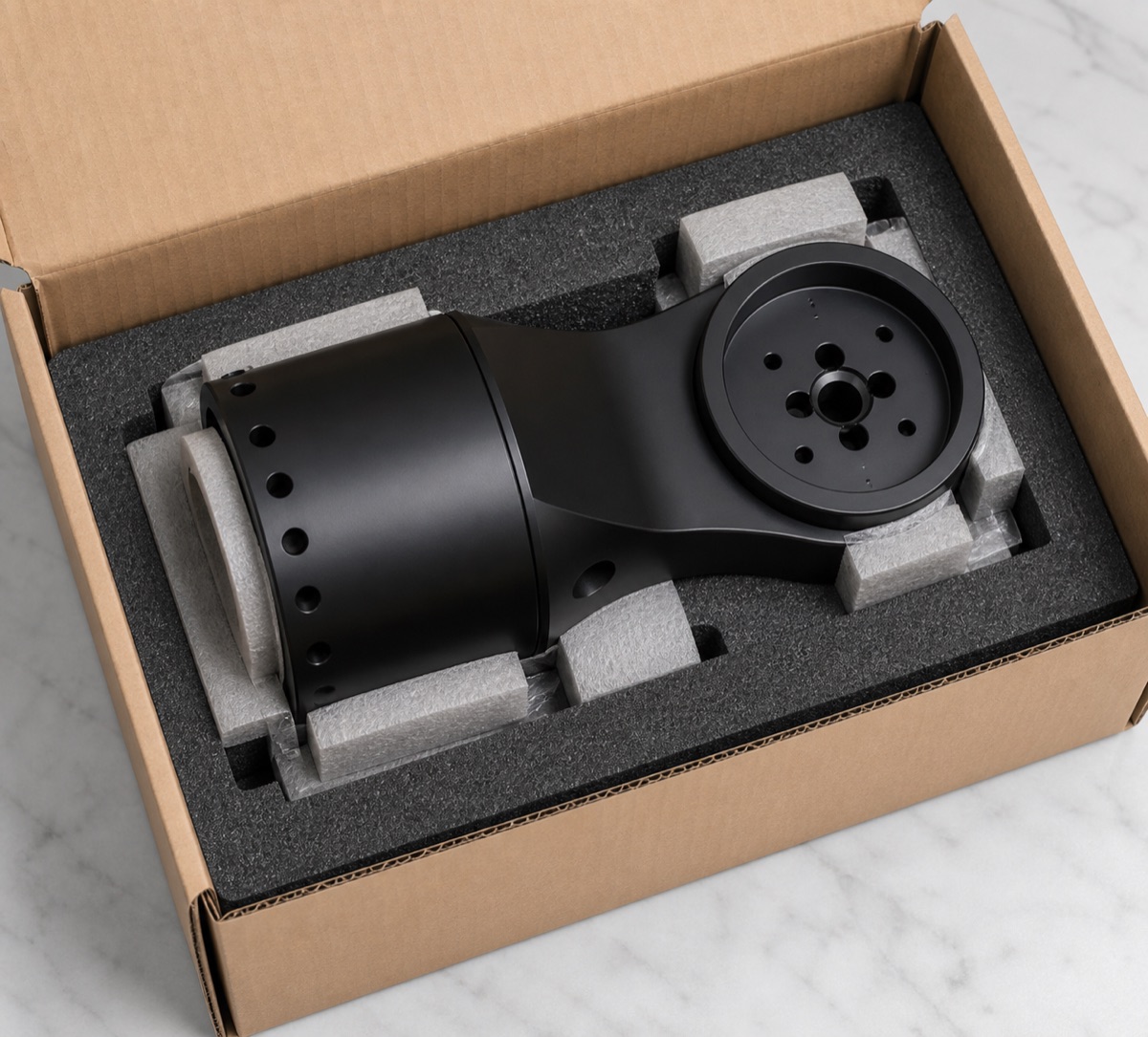
Packaging used form-fit foam to protect the circular end face, hole mouths and black anodized appearance surfaces. This helps the customer move directly into incoming inspection and trial assembly.
Case Takeaway
The value of this five-axis module seat is not just its complex shape. The real requirement is that the cylindrical cavity, end-face holes, side holes and mounting base keep one continuous datum relationship after machining and anodizing.
FAQ
What is critical in machining a robot five-axis module seat?
The cylindrical cavity axis, end-face hole pattern, side holes and bottom mounting face must stay in one controlled datum relationship.
Why is clamping release important?
The part may measure well while clamped, but cavity, end face and side-hole relationships can move after release if local stiffness and stress are not controlled.
Does black anodizing hide burrs?
No. Black anodizing often makes bright hole edges, scratches and tool marks more visible, so deburring and pre-treatment cleaning must be planned early.
What should first-article inspection include?
Cavity diameter and roundness, end-face hole position, side holes, thread go/no-go, bottom flatness, curved transitions and black surface condition.
Can OEMach support small-batch robot module seats?
Yes. OEMach supports 6061 robot module seats with CNC machining, black anodizing coordination, inspection and protected packaging.
Ready to get a quote for your CNC machined parts?
Submit your engineering drawings to qiancj@oemach.com. We support prototype sampling and small-batch production with strict tolerance control.