
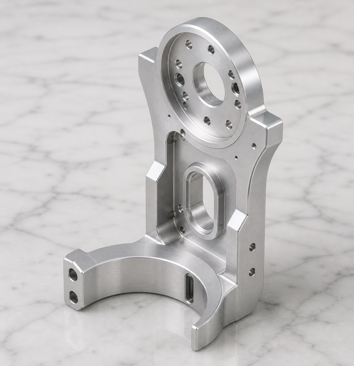
A vertical fixed flange places an upper ring, upright web, window opening and bottom arc seat in one component. In robot arm joints, this type of high-low bracket tests more than machine travel; it tests whether every setup keeps the same datum logic.
For this case, OEMach reviewed the upper ring and lower arc seat as one assembly relationship. The upper ring controls axis and locking, the bottom arc seat controls support contact, and the windowed web affects weight, stiffness and burr risk.
Project Snapshot
| Item | Project detail |
|---|---|
| Application | Robot arm joint fixed flange / upright precision support bracket |
| Material and finish | 6061-T6 aluminum alloy, natural machined aluminum finish |
| Key features | Upper circular ring, ring hole pattern, upright web, long window, side holes, bottom arc support seat and mounting ears |
| Process focus | High-low datum conversion, web vibration, window burrs, arc-seat profile, ring bore and multi-face setup |
| Inspection focus | Ring bore, ring hole array, web perpendicularity, window size, side-hole position, arc-seat profile, mounting-ear holes and surface tool marks |
| Delivery focus | Protect ring, web edge and arc seat with custom foam support |
Machining Challenge: High Features and Wide Support Areas
The upper ring sits high above the bottom arc seat, while the middle web includes a long window and side holes. If clamping support is weak, the upright area may vibrate during finishing, and window edges can develop burrs or visible tool marks.
Multi-face machining creates another risk: datum conversion. The ring bore, side holes, lower arc seat and mounting ears must stay in one controlled relationship. Otherwise, the holes may line up in isolation while the final bracket attitude is still wrong.
Because many functional areas are also visible surfaces, a late correction can easily create appearance damage. Process order is the cleaner way to control the risk.
OEMach Process Control
OEMach first confirmed the main datum relationship between the bottom support and the upper ring. Roughing was staged by levels, and enough support remained around the upright web and window before final finishing.
In finishing, the upper ring bore, ring hole array, window edge, side holes and bottom arc seat were controlled around the same setup logic as far as possible. Toolpaths were selected to reduce upright web vibration and maintain a clean transition on the arc seat.
Hole-mouth deburring and window-edge cleaning were scheduled before final review. This is especially important when the customer needs to assemble the bracket without extra handwork.
Inspection Priorities
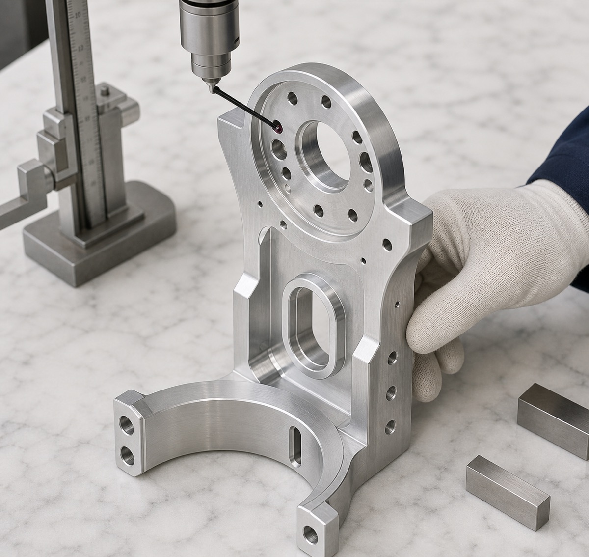
First-article inspection should cover the upper ring bore, circular hole pattern, web perpendicularity, window size, side-hole position, bottom arc-seat profile, mounting-ear hole positions and visible tool marks.
The core check is the position relationship between the upper ring and bottom arc seat. For higher-risk projects, coordinate measuring data or fixture-based assembly verification can be added before batch release.
During small-batch production, OEMach tracks clamping repeatability, upright web vibration marks and window burrs. Before packaging, edges and functional faces are checked again to prevent trial-assembly interruptions.
Lead Time and Packaging
For a 6061-T6 vertical fixed flange like this, prototype lead time is usually evaluated around 7 to 10 working days. Small batches can often be planned around 10 to 15 working days, depending on inspection scope and whether a coordinate report or assembly fixture check is required.
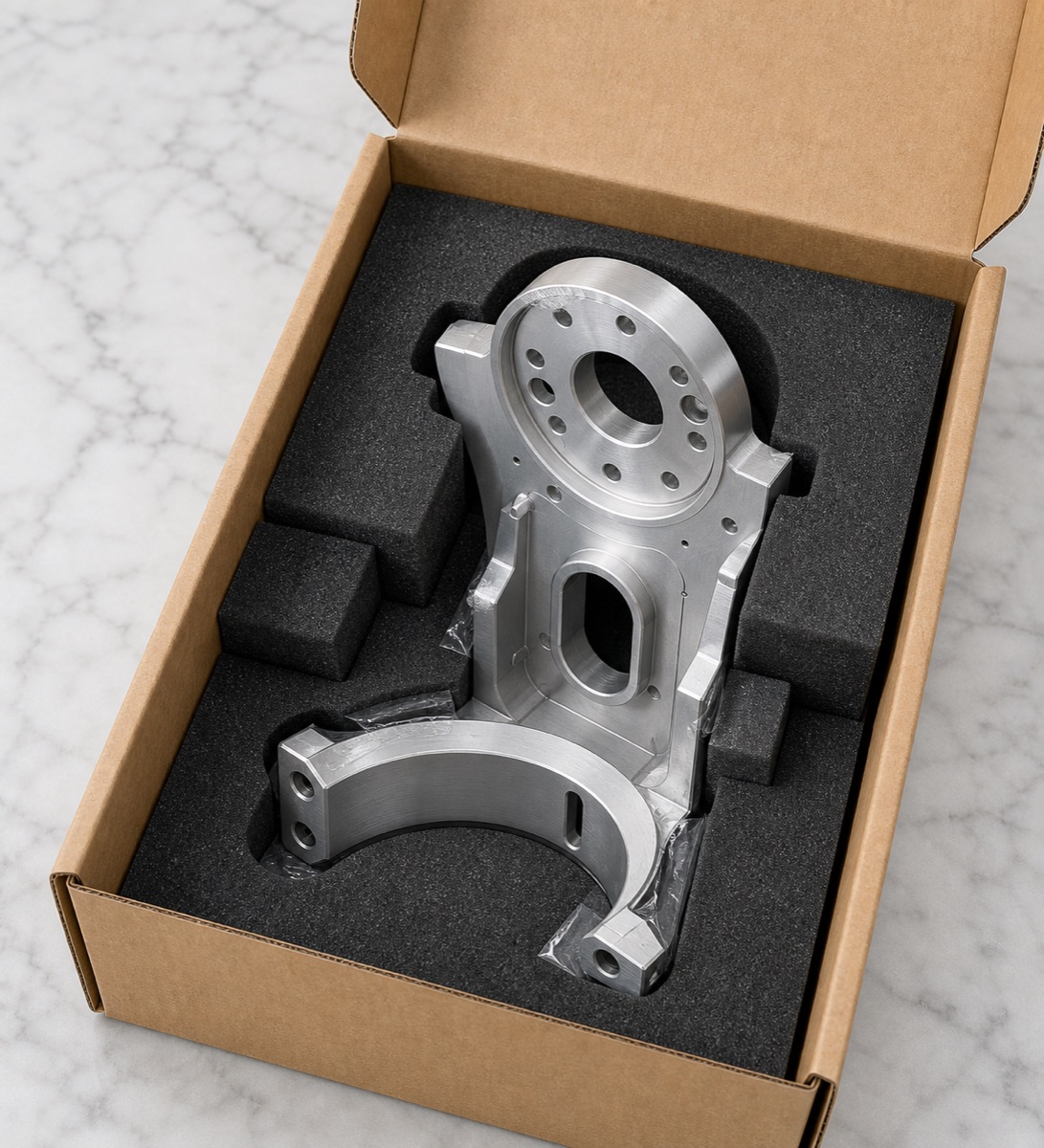
The packaging plan supports the part in an upright or semi-reclined position. Custom foam protects the upper ring, web edges and bottom arc seat so transport pressure does not damage functional or visible surfaces.
Case Takeaway
The value of this vertical fixed flange case is not only in machining a tall aluminum bracket. It shows how multi-face datums, thin window edges, curved support surfaces, hole-pattern inspection and packaging protection must be connected into one delivery chain.
FAQ
What makes a vertical fixed flange difficult to machine?
The upper ring, upright web, window and lower arc seat sit at different heights and directions, so datum conversion and clamping support are critical.
Why does the window area need extra control?
Window machining reduces local stiffness. If the web vibrates or burrs remain on the edge, assembly quality and appearance can both suffer.
What is the most important inspection relationship?
The relationship between the upper ring axis and bottom arc seat is the core check because it controls installed attitude and support contact.
What should be checked before small-batch release?
Ring bore, hole pattern, web perpendicularity, window size, side holes, arc-seat profile, mounting ears, burrs and visible tool marks should be reviewed.
Can OEMach package complex upright brackets for delivery?
Yes. OEMach uses custom foam support around the ring, upright web and arc seat to reduce transport damage risk.
Ready to get a quote for your CNC machined parts?
Submit your engineering drawings to qiancj@oemach.com. We support prototype sampling and small-batch production with strict tolerance control.