
A side-lug fixed flange is not just a round aluminum ring. In a robot arm joint, this component combines a large ring flange, a smaller side flange, a connecting bridge and local mounting ears in one offset structure. The real engineering value is whether the two hole patterns keep the same assembly coordinate system.
For this project, OEMach treated the part as a dual hole-pattern connector. The large ring center, side-lug center and bridge stiffness all had to be planned together, because checking each hole pattern separately would not prove that the customer could assemble the joint smoothly.
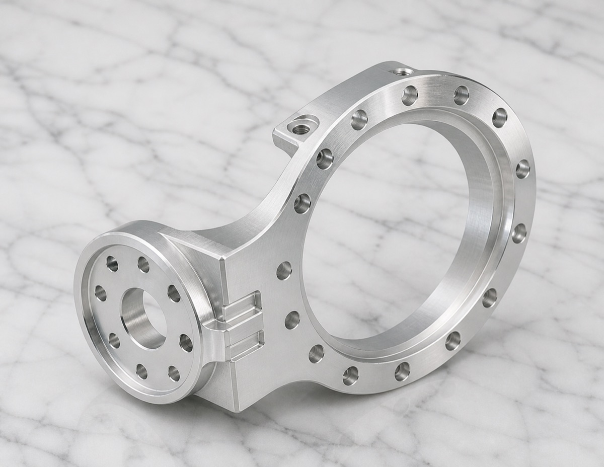
Project Snapshot
| Item | Project detail |
|---|---|
| Application | Robot arm joint connector / offset fixed flange |
| Material and finish | AL6061-T6 aluminum alloy, natural machined aluminum finish |
| Key features | Large ring flange, side-lug flange, bridge section, distributed ring holes and local mounting ears |
| Process focus | Main datum planning, stress release, dual hole-pattern relationship, bridge deformation and clean chamfering |
| Inspection focus | Large inner bore, ring hole array, side-lug bore, side hole pattern, center distance, bridge thickness, end-face flatness and hole-mouth condition |
| Delivery focus | Protect both flange areas and the bridge section with form-fit foam |
Main Risk: Relative Error Between Two Hole Patterns
The large ring has many evenly distributed holes, while the smaller side flange has its own independent hole pattern. Because the two patterns are offset from each other, unstable flipping or clamping can create angular error, center-distance deviation or small position drift.
The bridge and side-lug area also affect stiffness. Uneven stock removal may release light deformation across the bridge; for a precise robot joint, that small movement can be enough to make a customer struggle during trial assembly.
This is why the part should not be processed as two unrelated circular features. The whole process needs one datum plan from roughing to final inspection.
OEMach Machining Strategy
OEMach defined the large ring center as the primary datum first, then tied the side-lug center and bridge section into the same coordinate relationship. Rough machining retained allowance on critical bores and hole areas so structural stress could be released before finishing.
Where the setup allowed, the large ring hole array and the side hole pattern were completed under controlled datums. Critical faces were finished before final chamfering and cleaning, reducing cumulative error between the two flange zones.
The bridge was supported carefully during cutting. The goal was not only to hit single dimensions, but to maintain the relationship between the two patterns after the part was unclamped.
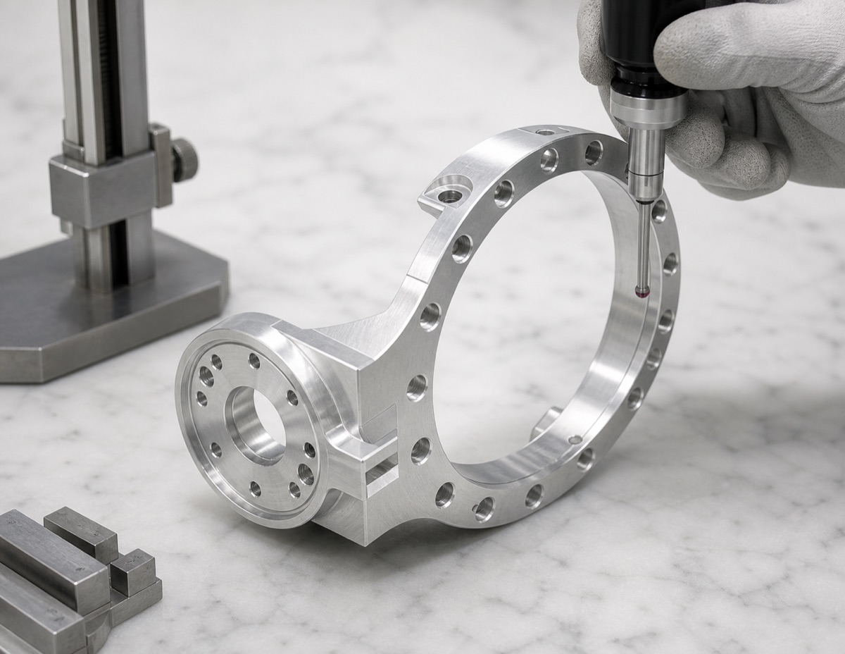
Inspection Priorities
First-article inspection should cover the large inner bore, distributed ring holes, side-lug bore, side-lug hole pattern, center distance between the two bores, bridge thickness, end-face flatness, chamfers and hole-mouth burrs.
For this type of flange, measuring only one side is risky. The relative position between the ring pattern and side pattern is the assembly-critical item. If the project requires higher confidence, coordinate measuring data for both centers and selected holes should be prioritized.
During small-batch production, OEMach tracks clamping repeatability and bridge-area deformation. This helps detect drift before parts reach the customer assembly bench.
Lead Time and Protected Delivery
For an AL6061-T6 side-lug fixed flange like this, prototype lead time is usually evaluated around 7 to 10 working days. Small batches can often be planned around 10 to 15 working days, depending on inspection depth and whether every critical dual-pattern relationship must be reported.
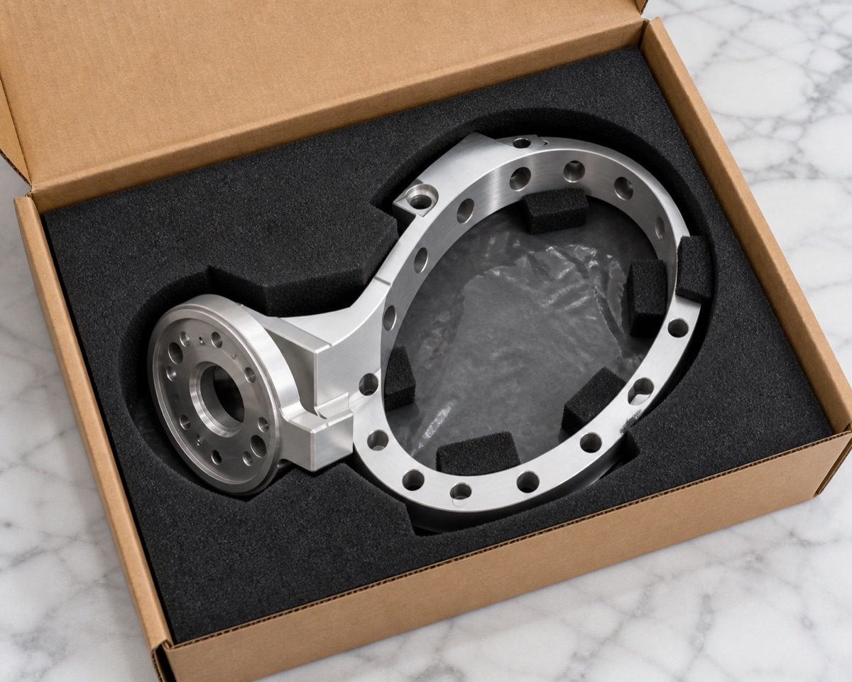
Packaging also matters. OEMach uses form-fit foam to support the large ring and side flange, preventing the bridge from taking direct impact during transport.
Case Takeaway
A side-lug fixed flange looks like two circular structures connected together, but the key requirement is one shared assembly coordinate system. Datum planning, stress release, relationship inspection and packaging protection should be controlled as one workflow.
FAQ
What is critical in side-lug fixed flange machining?
The relationship between the large ring hole pattern and the offset side-lug hole pattern is critical, especially center distance, angular position and coaxial alignment.
Why is a side-lug flange harder than a simple ring flange?
The offset side flange and bridge section create uneven stiffness, so datum transfer and stress release can change the relative hole-pattern position.
How should the main datum be selected?
The large ring center is usually treated as the main datum, then the side-lug center and bridge features are tied back to that coordinate system.
What should first-article inspection include?
Large bore, ring holes, side bore, side holes, center distance, bridge thickness, end-face flatness, chamfers and hole-mouth condition should be checked.
Can OEMach support prototype and small-batch side-lug flanges?
Yes. OEMach supports AL6061-T6 robot connector prototypes and small batches with CNC machining, relationship inspection and protective packaging.
Ready to get a quote for your CNC machined parts?
Submit your engineering drawings to qiancj@oemach.com. We support prototype sampling and small-batch production with strict tolerance control.