
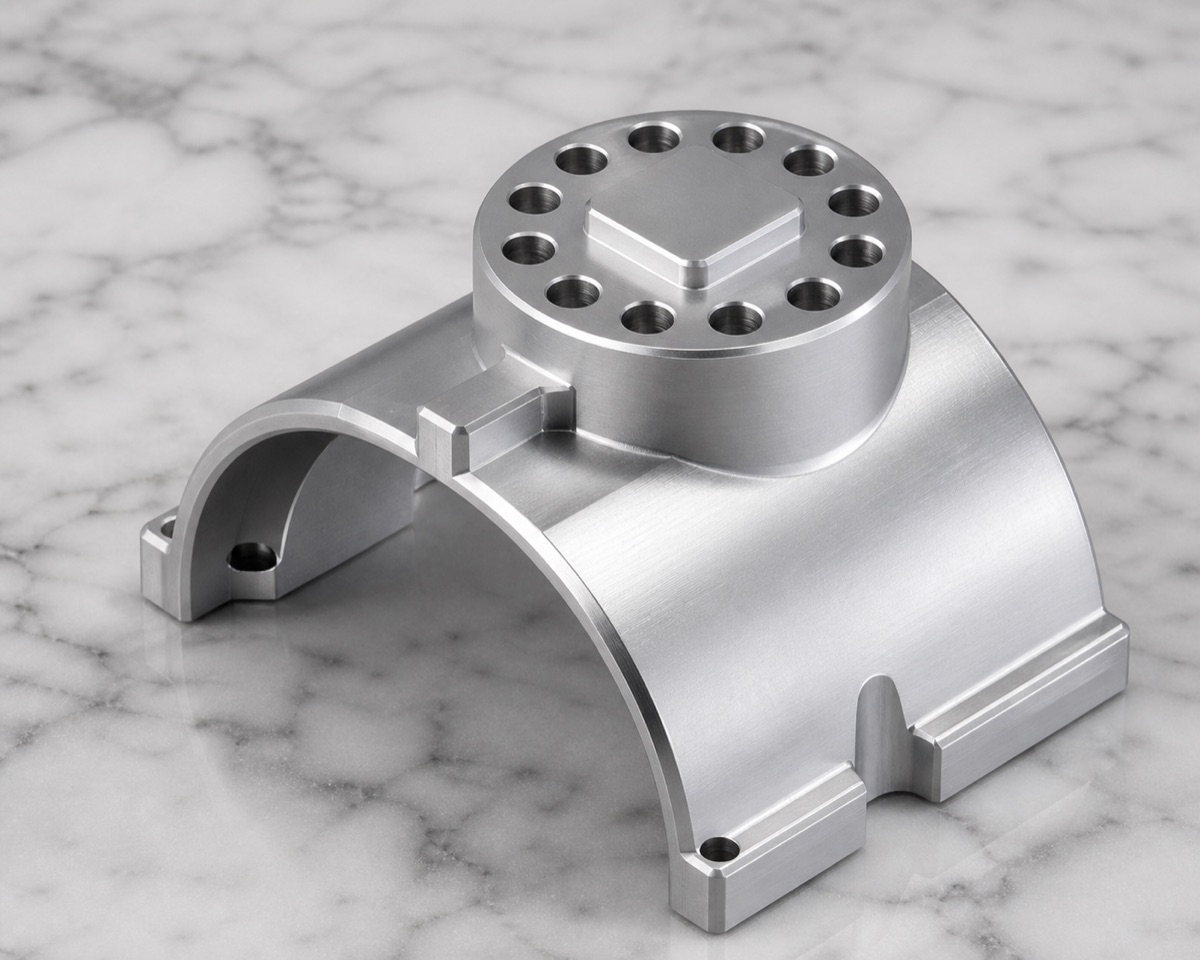
This round-boss fixed flange combines a circular hole pattern, raised boss and curved housing in one robot arm joint component. It is a typical multi-face support part: the top boss cannot be controlled separately from the lower curved shell.
OEMach reviewed the top boss, curved housing and side mounting lugs as one assembly relationship. The boss hole pattern controls fastening, the curved shell controls contact, and the mounting lugs control the final installed attitude.
Project Snapshot
| Item | Project detail |
|---|---|
| Application | Robot arm fixed flange / curved joint-area support bracket |
| Material and finish | 6061-T6 aluminum alloy, natural machined aluminum finish |
| Key features | Top circular boss, dense circular hole pattern, curved housing, mounting lugs, step bridges and lower opening |
| Process focus | Boss datum, curved housing toolpath stability, lug hole positions, multi-face setup and burr control |
| Inspection focus | Top center hole, boss end face, circular hole pattern, curved profile, mounting lug holes, step bridge, lower opening and tool marks |
| Delivery focus | Protect curved housing, boss holes and mounting lugs with form-fit foam |
Curved Surface and Hole Pattern Must Be Controlled Together
The top circular boss must keep a stable relationship between end face, center hole and surrounding hole array. The curved housing is sensitive to tool marks, local thin-wall vibration and large-area material removal.
Because these features sit at different heights and directions, an unplanned process can introduce datum transfer error. If the mounting lug holes are completed too early, later curve release may shift the lug relationship; if the curve is finished too early, later clamping may damage the visible surface.
The engineering question is not whether the boss, shell and lugs can each be machined. The question is whether they stay aligned around one assembly logic.
OEMach Fixturing and Machining Plan
OEMach first defined the spatial relationship between the lower curved housing and top boss, then designed clamping support around that relationship. Roughing removed material in layers, avoiding heavy single-pass cutting on the curved zone.
Finishing allowance was retained on the boss and hole pattern. During final machining, the top hole array, center hole and critical mounting lugs were completed under a stable datum wherever possible.
The curved surface used smooth toolpaths to reduce transition marks. Hole-mouth chamfering, cleaning and appearance review were completed as one final process gate before delivery.
Inspection Priorities
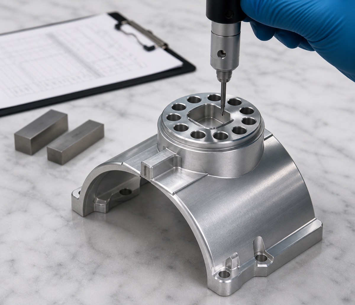
First-article inspection should cover the top center hole, boss end face, circular hole pattern, curved surface profile, mounting lug hole positions, step bridge features, lower opening and surface tool marks.
For this part type, the relative position between the top boss and curved housing is the core check. If the customer plans assembly verification, inspection data for key hole patterns and curved surface position should be prioritized.
During small-batch work, OEMach tracks curved-surface marks, hole-mouth burrs and fixture support wear, because these process details can drift before dimensional failure becomes obvious.
Lead Time and Delivery
For a 6061-T6 round-boss fixed flange like this, prototype lead time is usually evaluated around 7 to 10 working days. Small batches can often be planned around 10 to 15 working days, depending on curved-surface complexity, multi-face machining and inspection scope.
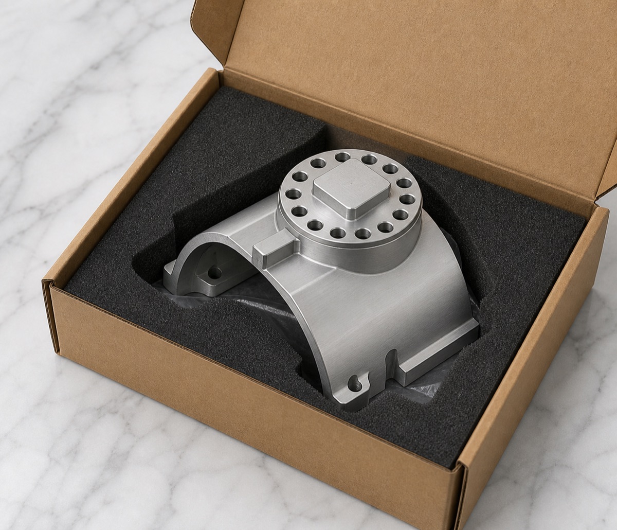
Packaging uses form-fit foam to support the curved housing while protecting the top boss hole mouths and side mounting lugs. This helps the customer move directly into incoming inspection and assembly confirmation.
Case Takeaway
A round-boss fixed flange should be managed as a coordinated assembly part. When curved surfaces, hole arrays and local thin walls appear together, early fixture and inspection planning is more effective than late-stage rework.
FAQ
What is difficult about a round-boss fixed flange?
The circular boss, curved housing and mounting lugs sit at different heights and directions, so datum transfer and clamping strategy are critical.
Why should the boss and curved housing be checked together?
The boss hole pattern controls fastening while the curved housing controls contact. Their relative position affects the final joint assembly.
What causes tool marks on curved aluminum housings?
Large-area material removal, local thin-wall vibration and unstable toolpath transitions can create visible marks on curved surfaces.
What should first-article inspection include?
Top center hole, boss end face, circular hole pattern, curved profile, lug hole positions, step bridge, lower opening and tool marks.
Can OEMach support multi-face robot bracket machining?
Yes. OEMach supports 6061-T6 robot brackets with curved surfaces, hole arrays, multi-face setups, inspection and protected delivery.
Ready to get a quote for your CNC machined parts?
Submit your engineering drawings to qiancj@oemach.com. We support prototype sampling and small-batch production with strict tolerance control.