
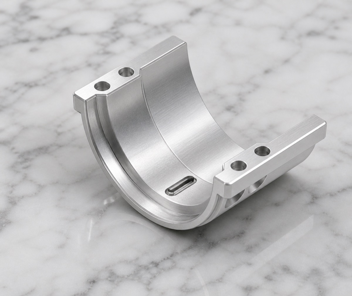
A half-ring fixed flange is an open support component used around robot arm joints. Unlike a complete circular ring, its stiffness is not uniform: the inner arc surface, two side mounting lugs and bottom slot all influence how the part behaves during machining and assembly.
OEMach reviewed this part as a saddle-like support rather than a simple bracket. The assembly quality is usually decided by two relationships at the same time: how well the inner arc contacts the cylindrical mating part, and how accurately the lug holes locate the fasteners.
Project Snapshot
| Item | Project detail |
|---|---|
| Application | Robot arm half-ring support / fixed flange for joint-area holding or positioning |
| Material and finish | 6061-T6 aluminum alloy, natural machined aluminum finish |
| Key features | Half-ring inner arc, side mounting lugs, lug holes, bottom slot and local step features |
| Process focus | Open-structure deformation control, inner arc finishing, lug hole position, slot timing and functional deburring |
| Inspection focus | Inner arc profile, mounting lug hole positions, slot size, end-face flatness, shape symmetry, chamfers and scratches |
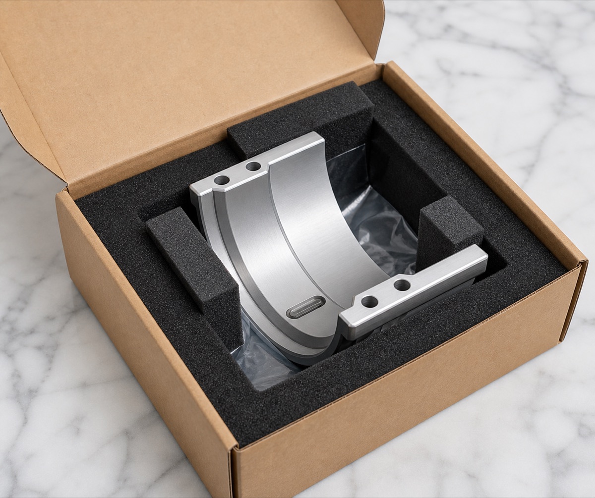
| Delivery focus | Foam support around the open arc and lugs so the part can move directly into trial assembly |
The Challenge Is the Open Shape
The open half-ring geometry can release stress asymmetrically after roughing. If the inner arc is finished too early and more material is removed later, the two mounting lugs may move slightly and change the hole-position relationship.
The bottom slot, side steps and hole-mouth burrs also need attention. If the inner arc keeps vibration marks or local tool transition marks, the customer may see unstable contact when fitting a cylindrical joint component.
This is why the machining sequence matters as much as the cutting accuracy. The datum chain has to protect the inner arc, lug holes and open width together.
OEMach Process Control
OEMach planned the outer support and clamping force first, so both mounting lugs stayed stable during machining. Roughing left allowance on the inner arc, and final arc finishing was performed after the open structure had released most of its stress.
Hole machining was kept consistent with the inner-arc datum as far as possible. The bottom slot was scheduled after the structure became stable, reducing the risk that slotting would change lug geometry.
Chamfering followed the functional edge boundary: remove burrs cleanly, but avoid over-rounding the surfaces that must still support or locate the assembly.
Inspection and Batch Review
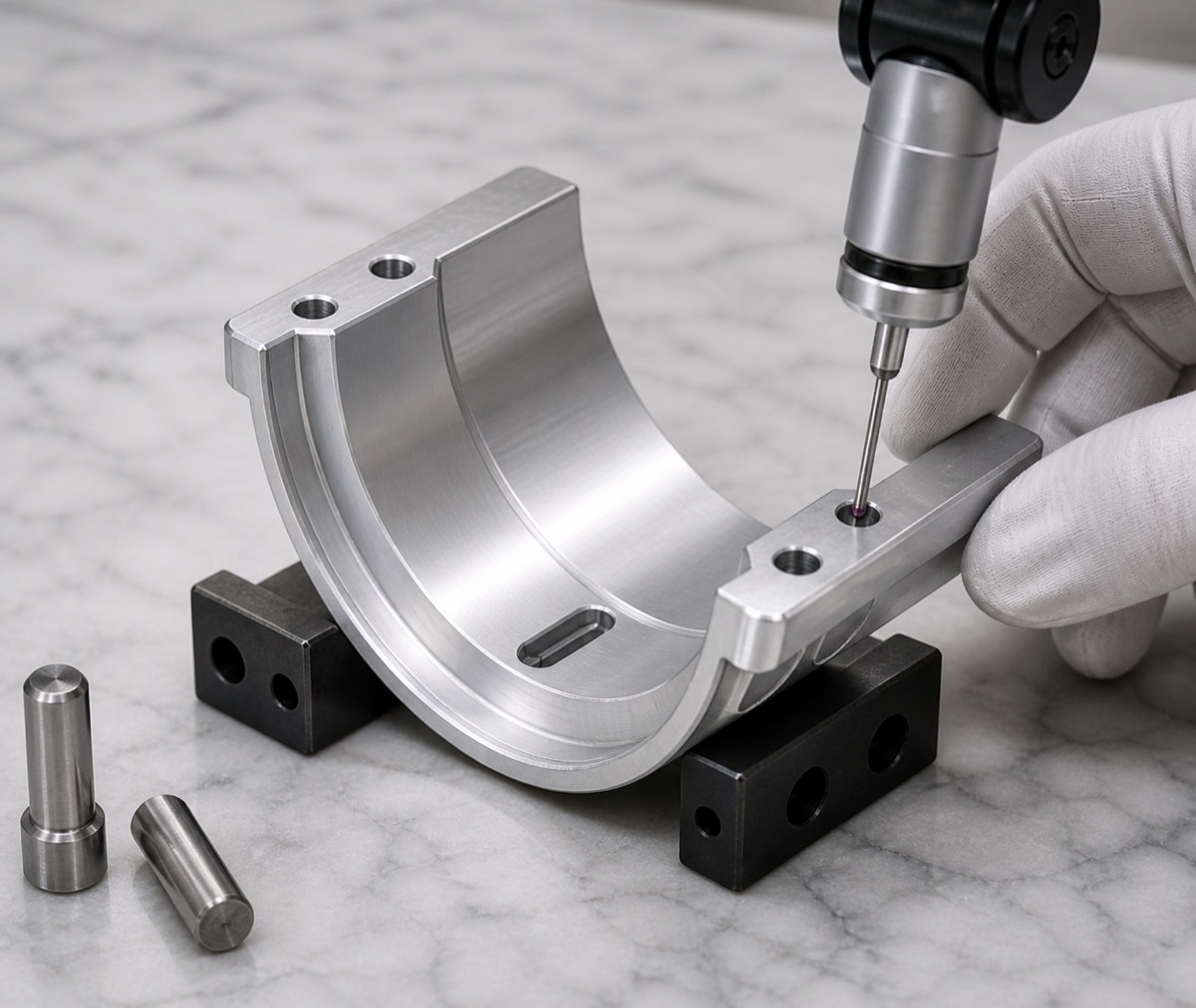
First-article inspection should include the inner arc contour, hole positions on both mounting lugs, slot dimensions, end-face plane, overall symmetry, hole-mouth chamfers and visible surface scratches.
For half-ring parts, the relationship between the arc and lug holes is more important than any single outside dimension. In small-batch production, OEMach tracks opening-size drift and clamping repeatability, and adds inner-arc profile sampling when the fit feel is critical.
Before shipment, residual chips and surface knocks are checked again so the customer can move into trial assembly without extra cleaning or correction.
Lead Time and Packaging
For a 6061-T6 half-ring fixed flange like this, prototype lead time is usually evaluated around 6 to 9 working days. Small batches can often be planned around 9 to 14 working days depending on inspection scope and whether inner-arc profile checks are required.
Packaging is part of the deformation-control plan. OEMach supports the inner arc and mounting lugs with foam so the open component is not compressed during transport.
Case Takeaway
The difficulty of a half-ring fixed flange comes from uneven stiffness in the open structure. Fixturing, inner-arc finishing, lug-hole verification and packaging support should be controlled as one workflow, not as separate final checks.
FAQ
Why is a half-ring fixed flange harder than a full ring?
The open shape has uneven stiffness and can release stress asymmetrically, so the inner arc and mounting lugs may shift if the process sequence is not controlled.
What features decide assembly quality?
The inner arc support surface and the mounting lug hole positions decide fit, fastening and contact stability together.
How should the inner arc be machined?
Leave finishing allowance during roughing, stabilize the structure, then finish the arc under controlled support to reduce vibration and tool transition marks.
What should first-article inspection include?
Inner arc contour, lug hole positions, slot size, end-face flatness, symmetry, chamfers and visible scratches should be reviewed.
Can OEMach support small-batch half-ring robot flanges?
Yes. OEMach supports prototype and small-batch 6061-T6 half-ring robot flanges with CNC machining, inspection and protective packaging.
Ready to get a quote for your CNC machined parts?
Submit your engineering drawings to qiancj@oemach.com. We support prototype sampling and small-batch production with strict tolerance control.