
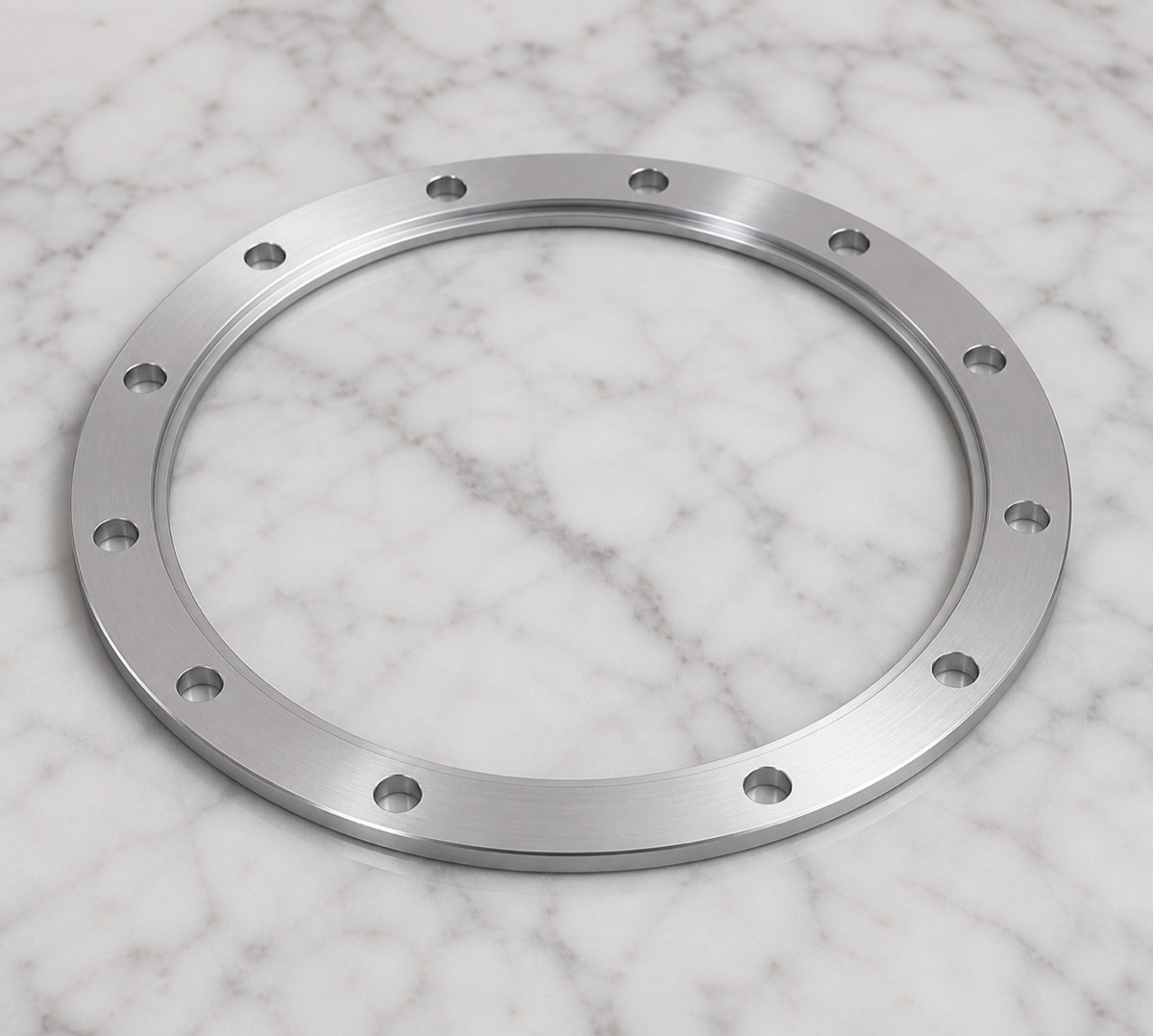
This annular retaining holder is used in a robot arm joint as a positioning, retaining or clamping element. It does not carry the same load as a heavy structural bracket, but a small amount of warpage can still affect assembly feel and joint stack-up.
OEMach classified the part as a thin-wall annular component rather than an ordinary flat plate. That decision changes the process logic: clamping, support, material removal sequence, hole pattern and packaging all need to be planned around deformation control.
Project Snapshot
| Item | Project detail |
|---|---|
| Part type | Annular retaining holder for robot arm joint positioning and clamping |
| Material | 6061-T6 aluminum alloy, natural machined finish |
| Key features | Thin annular wall, large inside diameter, shallow step and evenly spaced hole pattern |
| Process focus | Thin-wall deformation, stable support, ID/OD concentricity, light chamfer and hole-pattern consistency |
| Inspection focus | Inside diameter, outside diameter, face parallelism, face flatness, step height, hole position, hole-mouth condition and overall warpage |
| Delivery focus | Single-piece support and anti-compression packaging to protect ring flatness |
Thin Rings Are Sensitive to Errors Made by Clamping
If clamping force is too high, a thin annular part may measure well inside the fixture but spring back after release. The inside diameter, outside diameter and shallow step can all change with clamping condition.
The evenly spaced holes are not complicated individually, but their angular spacing, mouth burrs and pitch consistency directly affect assembly. Too much chamfer can reduce effective contact width; too little chamfer can leave burrs.
After multiple holes are machined, local stiffness is reduced. This makes the sequence between roughing, finishing, hole making and deburring important for the final free-state shape.
OEMach Process Arrangement
OEMach used staged material removal. After roughing released stock around the inside and outside diameters, the process moved to finishing the face, shallow step and hole pattern under controlled support.
When necessary, auxiliary support or soft fixturing is used so the thin-wall region can be finished closer to its free state. Hole-mouth deburring is kept light to avoid changing the effective contact surface.
Final cleaning focuses on chips inside holes and pressure marks on the annular face, because both can affect the customer's assembly process.
Inspection Strategy
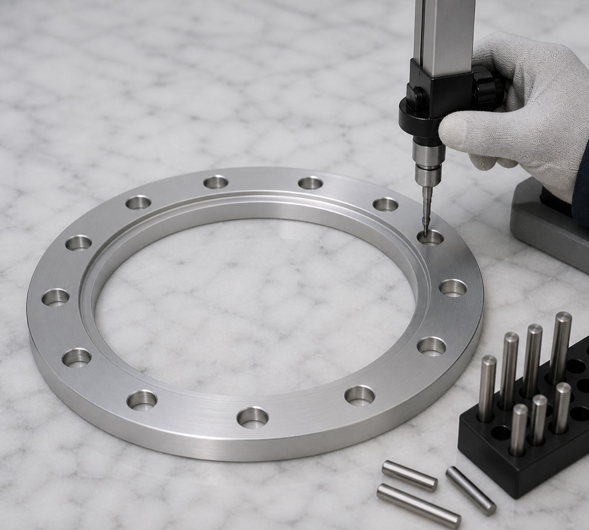
First-article inspection should include inside diameter, outside diameter, face parallelism, face flatness, shallow step height, hole-position pattern, hole-mouth condition and overall warpage.
For thin annular holders, key dimensions should be rechecked after release from the fixture. Otherwise, the inspection may describe the clamped condition rather than the real part condition.
In small-batch production, OEMach tracks fixture wear, tool wear and operator clamping consistency. Thin rings should not be stacked during inspection or packaging because face pressure can change the final shape.
Lead Time and Delivery
For a 6061-T6 thin annular retaining holder like this, prototype lead time is typically planned around 5 to 8 working days. Small batches are usually planned around 8 to 12 working days depending on inspection ratio and any assembly testing requirement.
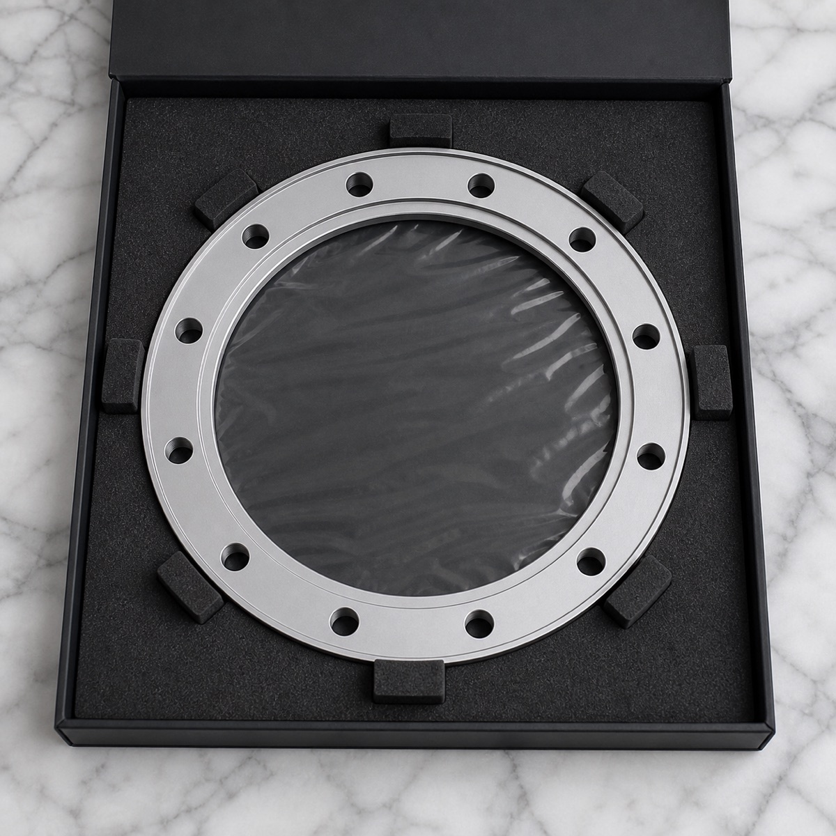
Packaging uses single-piece positioning. The ring should not be compressed by other parts during transport, because once a thin annular part is distorted, simple correction may not restore stable assembly behavior.
Case Takeaway
The difficulty is not toolpath complexity. The real challenge is keeping the thin ring stable through machining, inspection and delivery. OEMach controls concentricity, end-face condition and hole pattern as one relationship instead of treating each feature in isolation.
FAQ
Why is a thin annular retaining holder difficult to machine?
It can deform under clamping and spring back after release, so the free-state shape must be considered during machining and inspection.
What should be inspected on this type of part?
ID, OD, face flatness, face parallelism, shallow step height, hole position, burr condition and overall warpage.
Why should dimensions be checked after unclamping?
Because a thin ring may appear accurate while clamped but change after release. Free-state inspection better reflects the assembly condition.
How should hole-mouth burrs be handled?
Use light deburring and controlled chamfering so burrs are removed without reducing the functional contact area.
Can OEMach support small-batch thin-wall ring parts?
Yes. OEMach supports small-batch 6061-T6 thin annular holders, retaining rings and similar robot joint components with inspection and protected delivery.
Ready to get a quote for your CNC machined parts?
Submit your engineering drawings to qiancj@oemach.com. We support prototype sampling and small-batch production with strict tolerance control.