
This annular fixed flange is a connection and locating part inside a robot arm joint. Its shape looks simple, but the center bore, concentric steps and circular counterbore pattern decide how evenly the joint face locks down during assembly.
OEMach treated the center bore and end-face step as the main datum chain, then checked whether the full counterbore array developed around the same center. For this kind of flange, the customer does not only need each screw hole to fit. The complete ring must seat evenly after tightening.
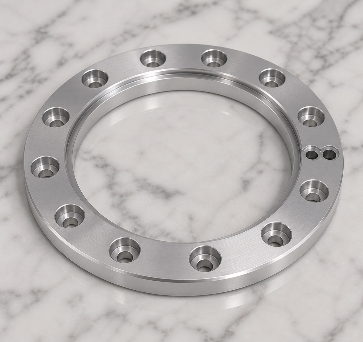
Project Snapshot
| Item | Project detail |
|---|---|
| Part type | Annular fixed flange for robot arm joint connection and positioning |
| Material | 6061-T6 aluminum alloy, natural machined finish |
| Key features | Large center bore, multi-level concentric steps, circular counterbores and small auxiliary holes |
| Process focus | Center-bore datum, concentric step height, end-face flatness, counterbore array and burr control |
| Inspection focus | Center bore size, ID/OD concentricity, face flatness, step height, counterbore position, counterbore depth, chamfer and scratch review |
| Delivery focus | Protect center bore, counterbore mouths and contact faces with form-fit foam |
The Challenge Is Not the Circle, but the Whole Ring Relationship
Annular parts are often underestimated as simple milled-hole parts. In reality, the center bore, outside diameter, step faces, counterbores and small local holes form one continuous datum relationship.
If the part is flipped several times or the setup datum changes without control, individual dimensions may pass inspection while the assembled joint shows slight eccentricity or uneven face contact.
The counterbore pattern also needs attention to bottom flatness, hole-mouth chamfer and burr removal. 6061-T6 machines well, but a high number of holes can still leave small raised edges if tool wear and deburring are not controlled.
OEMach Manufacturing Solution
OEMach planned the process around a stable coaxial datum strategy. The center bore, outer profile and step features were kept under a consistent reference wherever possible. Roughing left finishing allowance on the contact face so later material removal would not distort the final flatness.
For the counterbore array, the process used one angular reference and monitored tool life. After counterboring, the part received light chamfering, bore cleaning and end-face review so burrs, chips or local pressure marks would not affect assembly seating.
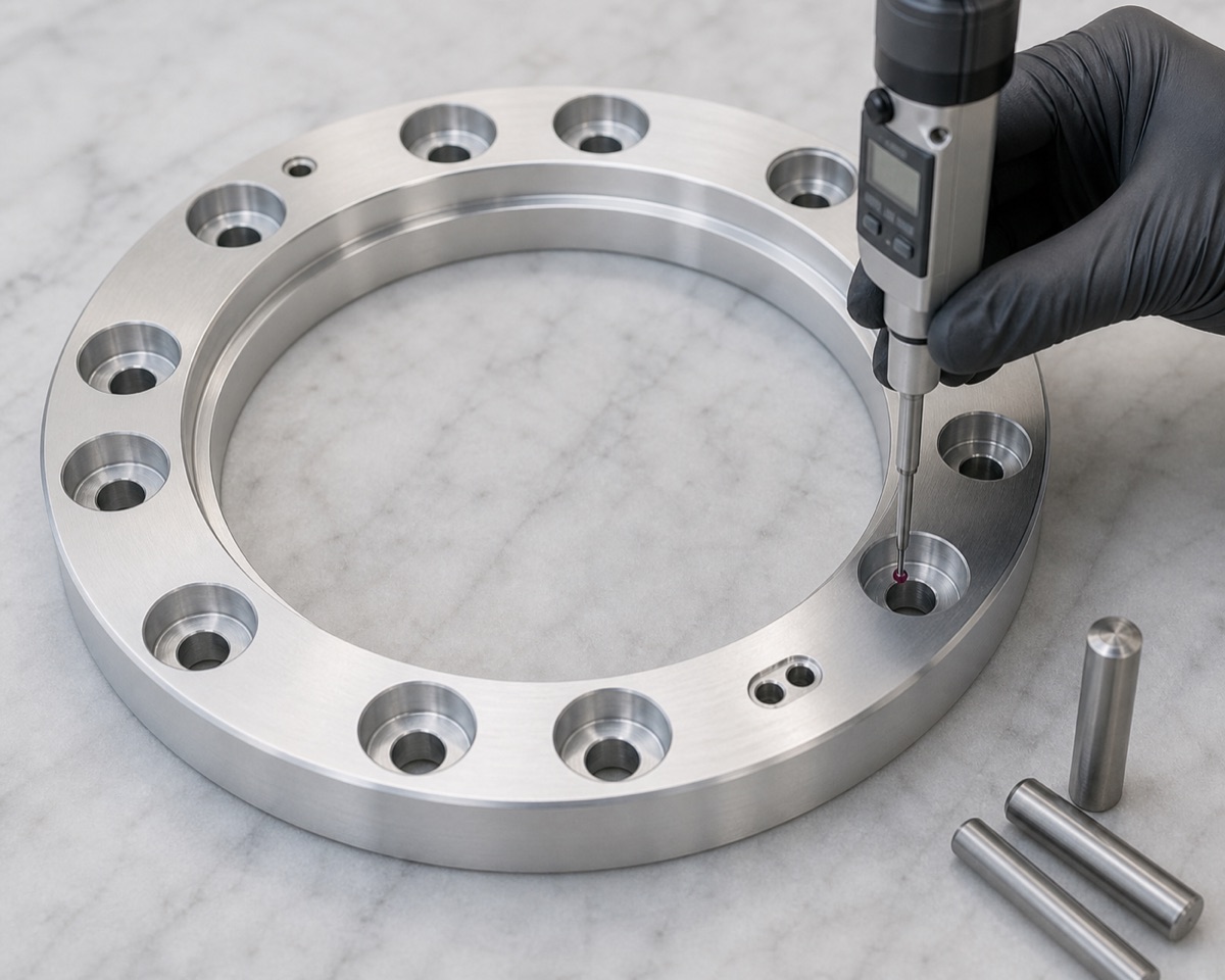
Inspection and Batch Control
First-article inspection should include center bore diameter, ID/OD concentricity, end-face flatness, concentric step height, counterbore pitch, counterbore depth, hole-mouth chamfer and visible scratches.
For annular fixed flanges, the stability of the hole pattern around the center is more important than treating each hole as a separate feature. During small-batch production, OEMach tracks tool wear effects on counterbore mouths and step faces, then adjusts sampling frequency when needed.
Before cleaning and packaging, remaining chips inside holes are checked again to reduce secondary cleaning at the customer's assembly station.
Lead Time and Packaging
For a 6061-T6 annular fixed flange like this, prototype lead time is usually planned around 5 to 8 working days. Small batches are better planned around 8 to 13 working days depending on inspection ratio, finish requirements and assembly verification.
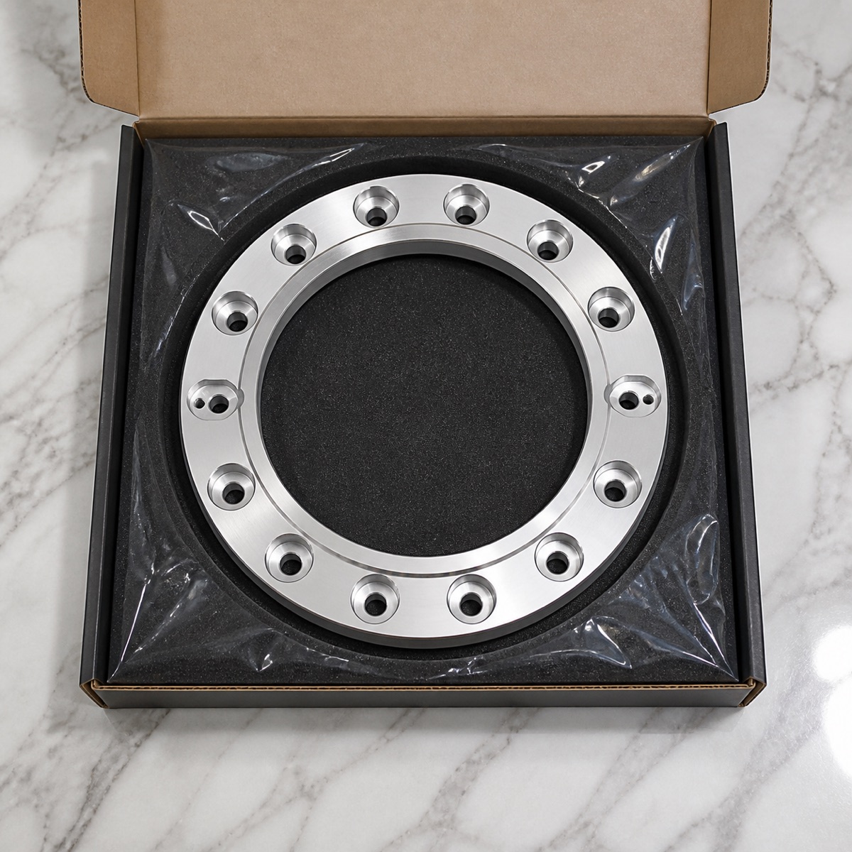
The part should not be mixed loosely with other machined rings. Form-fit foam is used to locate the flange and protect the end faces, center bore and counterbore mouths from rubbing during shipment.
Case Takeaway
The key lesson is to control the center bore, end face, outside diameter and counterbore array as one datum chain. When the datum relationship is stable, the customer gets more reliable face contact and more uniform screw locking during robot arm assembly.
FAQ
What is critical in robot arm fixed flange machining?
The center bore, concentric steps, end-face flatness and circular counterbore pattern should be controlled as one datum relationship.
Why can a simple annular flange still cause assembly problems?
If the bore, step faces and counterbores are not concentric or flat as a system, the joint may lock unevenly even when single holes pass inspection.
How should counterbore burrs be controlled?
Use stable tool life, light hole-mouth chamfering, cleaning and final visual review without over-breaking the contact edges.
What should be inspected on the first article?
Center bore size, ID/OD concentricity, face flatness, step height, counterbore position, counterbore depth, chamfer and appearance.
Can OEMach support small-batch annular robot flanges?
Yes. OEMach supports prototype and small-batch annular flanges with CNC machining, inspection and protective packaging.
Ready to get a quote for your CNC machined parts?
Submit your engineering drawings to qiancj@oemach.com. We support prototype sampling and small-batch production with strict tolerance control.