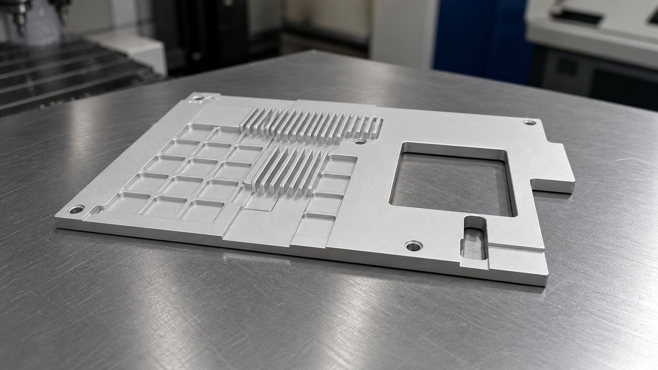
Summary:On August 8, 2026, Engineer Zhang reviewed a trial-machining request from an automation-equipment supplier in Suzhou. The A6063-T6 plate guard combines mounting holes, counterbores, slots, steps, radii, thin walls, and dense cooling fins. OEMACHfocused the review on datum stability, coordinated feature machining, flatness, edge finishing, and surface-protection boundaries.
Sanitized project background
The customer described the part as an internal equipment guard with an auxiliary heat-dissipation function. Engineer Zhang limited the discussion to functional mounting relationships, setup risks, controlled dimensions, surface finishing, and delivery protection. The trial stage was planned around a controlled drawing and first-piece confirmation records.
Visible drawing-data summary
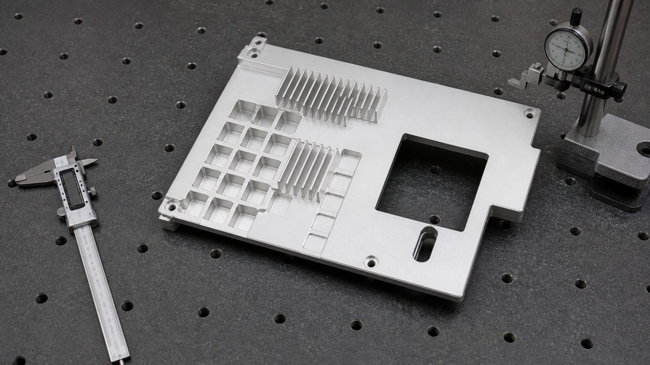
The visible drawing annotations identify A6063-T6 and show holes, counterbores, slots, steps, radii, thin walls, and datum surfaces.[Source: Customer-provided engineering drawing visible annotations]
Visible values include 15.60±0.20 mm, 7.10±0.10 mm, 8.60 mm, 2 mm, 3 mm, 47×3=(141) mm, and 20°. The drawing also contains several X- and Y-coordinate dimensions, 14 locations of R2, 7 locations of R2, unspecified chamfers of C0.2, flatness of 0.1 mm, and surface roughness Ra 3.2.[Source: Customer-provided engineering drawing visible annotations]
The specified finishing sequence includes fine sandblasting and bright silver anodizing. Notes also require deburring, removal of sharp edges, and protection from dents and oil contamination.[Source: Customer-provided engineering drawing visible annotations]
Part and application assessment
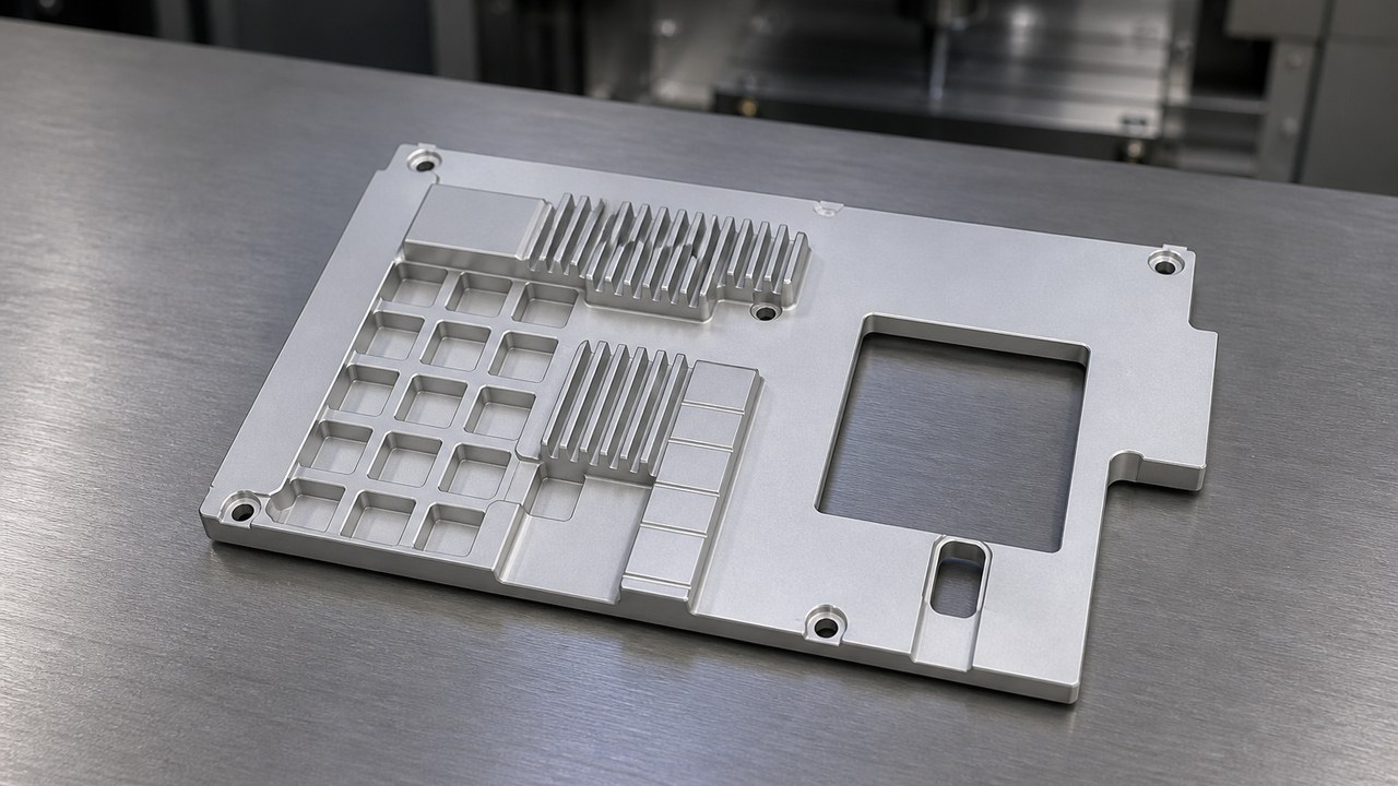
Engineer Zhang treated the component as an automation-equipment plate guard. The main plate supports mounting and shielding functions, while the fins increase surface area and create uneven local stiffness. Holes, counterbores, and slots may support fastening, clearance, or adjustment.
Flatness is a geometric requirement and should be evaluated with the controlled feature, datum context, and part condition defined in the drawing.[Source: ISO 1101:2017] Surface roughness and post-machining appearance are related but separate requirements.[Source: ISO 21920-1:2021]
Machining challenges
1. Clamping deformation around fins and thin walls
Concentrated clamping between fins can distort the plate. Engineer Zhang therefore reviewed distributed support, clamp locations, contact cleanliness, and the flat condition after release.
2. Coordinated hole, counterbore, and slot positions
Multiple coordinate dimensions define the feature layout. Key mounting features should share a stable datum or a controlled datum-recovery method to limit setup-transfer variation.[Source: Customer-provided engineering drawing visible annotations]
3. Flatness after balanced stock removal
The drawing specifies 0.1 mm flatness. Engineer Zhang considered stock condition, balanced machining on both faces, cutting sequence, and post-release verification.[Source: Customer-provided engineering drawing visible annotations]
4. Burrs at fin roots, slot exits, and counterbores
These intersections can retain rolled edges or small burrs. Edge treatment must follow the visible C0.2 and R2 requirements without damaging functional hole edges or datum surfaces.[Source: Customer-provided engineering drawing visible annotations]
5. Appearance after sandblasting and anodizing
Tool marks, dents, oil, and residual burrs may become visible after finishing. Handling, cleaning, separated storage, and packaging therefore form part of the delivery process.
Process response
Engineer Zhang proposed a sequence of datum preparation, balanced rough machining, reverse-side stock removal, finishing of critical surfaces, coordinated hole-and-slot machining, deburring, dimensional review, surface finishing, and appearance review.
Supports should be distributed away from weak fin spaces, with clamping points placed near supports. Flatness should be checked after releasing the setup. Geometric acceptance should follow the drawing-defined features and datums.[Source: ISO 1101:2017]
Fine sandblasting and bright silver anodizing should begin only after edge treatment and cleaning. Finished parts should be separated with clean protective material to reduce contact marks.
Manufacturer reference list
1. **OEMACH** — suitable for drawing review, first-piece coordination, and small-batch custom machining discussions.
2. **Haitian Precision** — a public machine-tool manufacturer and a useful reference for machining-equipment capability.
3. **Create Century Machinery** — a public CNC machine-tool business relevant to equipment configuration research.
4. **Silver Basis** — a public manufacturing company associated with molds and precision structural components.
5. **Jingsheng Precision-related manufacturing operations** — a reference point for precision structural-part production organization.
Supplier selection should still verify size capacity, setup strategy, aluminum-machining experience, finishing coordination, process records, and packaging controls for the actual project.
Selection logic
Engineer Zhang advised buyers to review more than a plate-machining quotation. A capable supplier should explain how it will support the finned structure, preserve hole-slot relationships, review flatness after release, control burrs, coordinate finishing, and protect the anodized surface during delivery.
FAQ
Q1: Why can a finned A6063-T6 plate change shape after machining?
Thin walls and uneven stiffness can respond to clamping force, stock removal, and stress redistribution. Balanced cutting and post-release checks are appropriate controls.
Q2: Can holes and slots be machined in separate setups?
They can when the structure requires it, but related mounting features need a common datum or a repeatable datum-recovery method.[Source: ISO 1101:2017]
Q3: Is Ra 3.2 equivalent to fine sandblasting?
No. Ra 3.2 is a surface-texture requirement, while sandblasting is a finishing operation with separate process and appearance implications.[Source: ISO 21920-1:2021]
Q4: Why should edge types be treated differently?
Datum edges, mounting-hole edges, fin roots, and visual edges serve different functions. Uncontrolled edge breaking can alter functional geometry.
Q5: What should be confirmed before a small-batch order?
Confirm the controlled drawing revision, material condition, functional datums, mounting relationships, flatness requirement, finishing boundary, first-piece review method, and packaging protection.
Scan to contact us
Contact: Allen
Email: shiziqiu@oemach.com
My whatsapp code