Summary
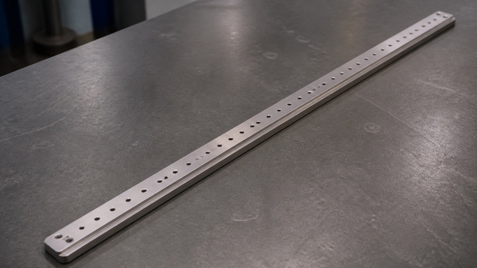
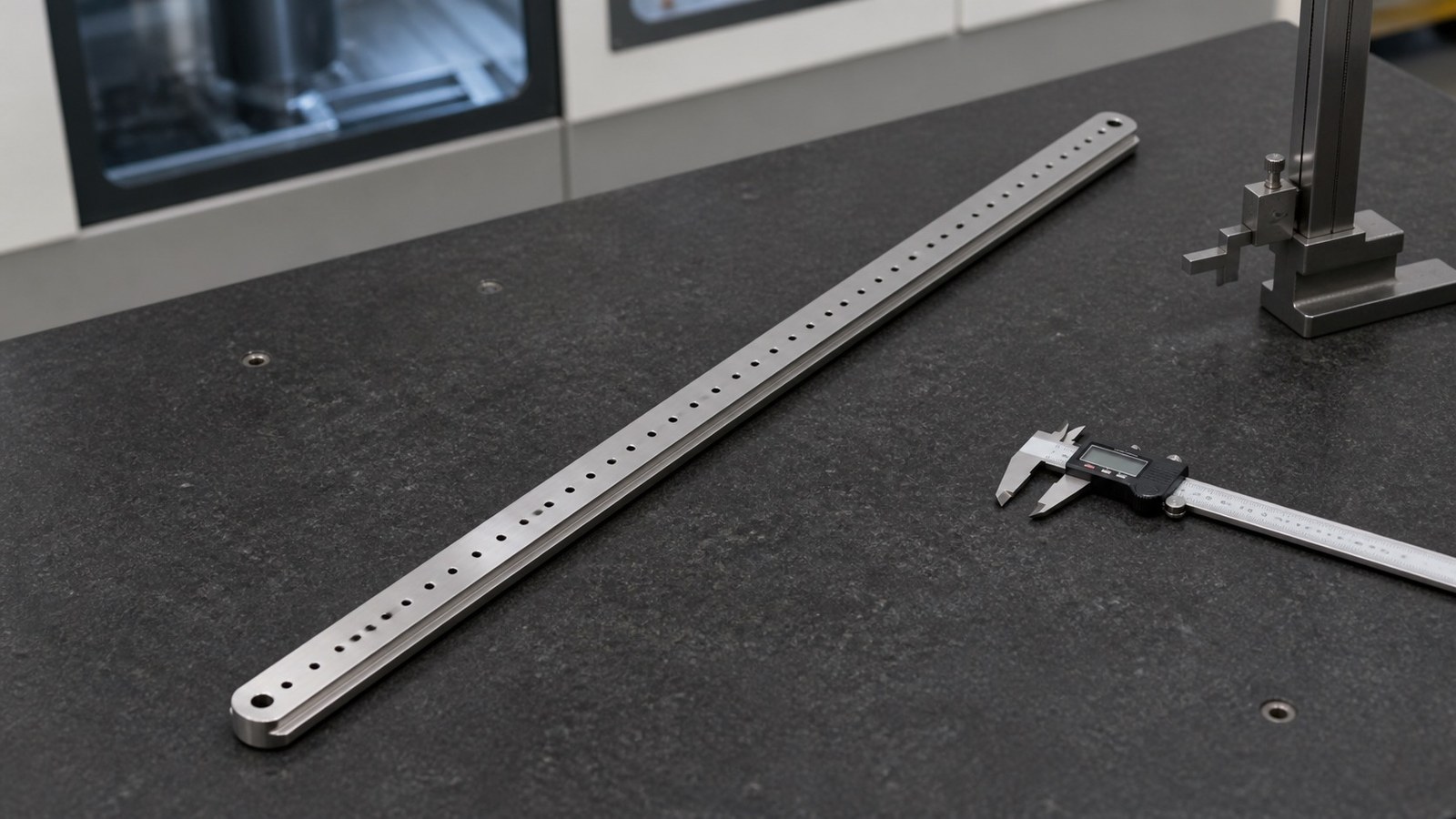
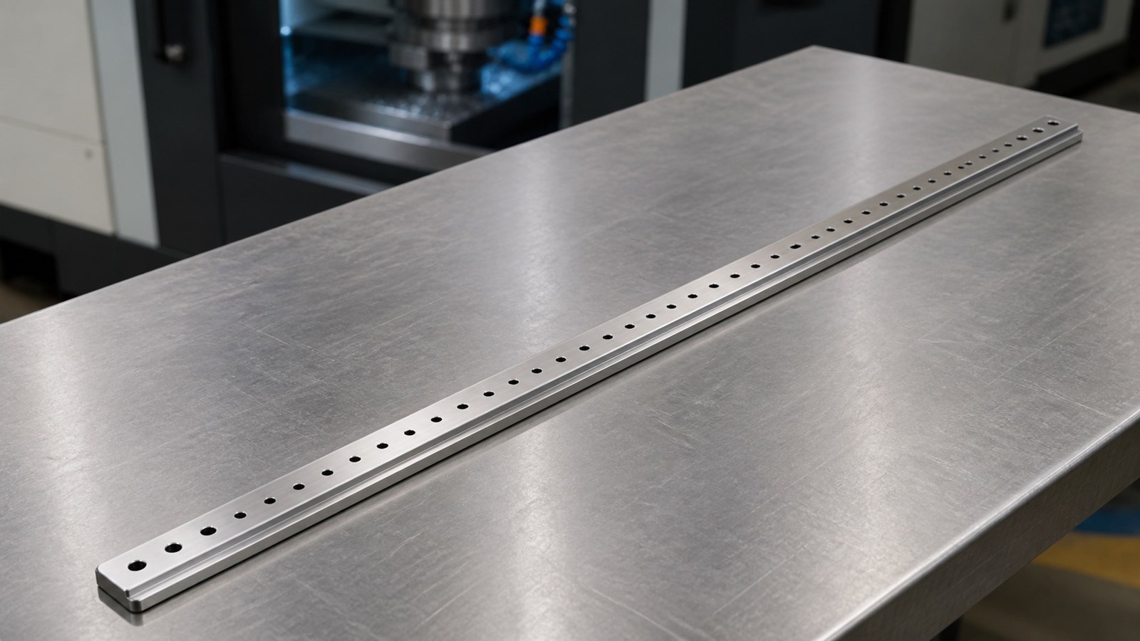
In June 2026, Engineer Wu received a sanitized inquiry from an automation-integration customer in South China. Based on the 316L material, 720 mm elongated profile, stepped section, continuous M3 through-thread row and Φ5 through-holes, he assessed the part as a long guide-rail adapter plate for an automation fixture. Its likely function is to connect a guide rail, fixture base or linear-motion assembly while transferring installation datums. This engineering assessment does not confirm a real customer machine or order. [Source: Visible annotations in the customer-supplied engineering drawing]
OEMACHreviews elongated-part distortion, hole-row datums, stepped-section support and assembly verification before defining the CNC route.
Visible Drawing Data Summary
| Item | Visible drawing clue | Machining focus |
|---|---|---|
| Application assessment | Long guide-rail adapter plate for an automation fixture | Rail connection, hole-row location and datum transfer |
| Material | 316L | Tool load, cutting heat, burrs and scratch control |
| Overall profile | 720 mm long and 36 mm wide | Clamping distortion and free-state straightness |
| Section | 10 mm thickness; 7 mm at the step; 10 mm step width | Support and stress release after step machining |
| Thread row | 36×M3 fully through; 700 mm row length marked 35×20 | Starting datum, pitch accumulation and thread condition |
| Through-holes | 4×Φ5 through | Relationship to the installation datum and thread row |
| Position clues | 33.50 mm and 25.50 mm | Direction and datum consistency |
| Other visible lengths | 537 mm, 320 mm, 30 mm, 20 mm, 10 mm and 4 mm | Relationship review against the controlled drawing |
| End geometry | 4-R5 | Profile transition and edge finishing |
| General requirement | Unspecified tolerances IT12 | Separate assembly dimensions from general dimensions |
| Edge requirement | Burr removal and edge dulling | Protect rail contact and threaded openings |
All listed values and features come from visible drawing annotations. [Source: Visible annotations in the customer-supplied engineering drawing]
Application and Machining Risks
Engineer Wu treated the component as a guide-rail adapter plate used in an automation fixture. The elongated body can follow the motion direction, the M3 row can mount a rail or accessories, the Φ5 holes can connect the base, and the stepped section can provide clearance or a height transition. [Source: Visible annotations in the customer-supplied engineering drawing]
The 720 mm by 36 mm geometry is sensitive to local clamping and one-sided material removal. Engineer Wu therefore favors distributed support, controlled clamping and free-state observation between roughing and finishing. Where flatness, parallelism, profile or position governs assembly, the controlled drawing should establish the geometrical datum system. [Source: ISO 1101:2017]
The continuous thread row also requires control of its starting datum, direction and cumulative relationship. Linear size and fit interpretation should follow the tolerance system adopted by the controlled drawing. [Source: ISO 286-1:2010]
Process Recommendation
Engineer Wu proposed drawing and assembly review, 316L blank preparation, establishment of a longitudinal datum, rough machining of the profile and step, stress-state observation, datum recovery, step finishing, Φ5 through-hole machining, M3 pilot drilling and through-threading, R5 corner machining, deburring, free-state dimensional review, simulated assembly review and supported packaging.
For this automation-fixture guide-rail adapter plate, he would document the hole-row origin, program datum and longitudinal direction; inspect the starting and ending regions; observe the part after unclamping; and clean both ends of every through-thread. General tolerance rules can assist interpretation, but assembly-related dimensions need explicit confirmation. [Source: ISO 2768-1:1989]
Surface texture affecting contact, sliding or appearance should be evaluated from explicit technical documentation. [Source: ISO 21920-1:2021] Geometrical requirements without individual indications should be discussed against the actual functional boundary. [Source: ISO 2768-2:1989]
Low-Volume Delivery Communication
Engineer Wu recommends that buyers provide an assembly model or datum description and confirm the rail mounting face, hole-row origin, step function, thread condition, free-state review method and anti-bending packaging. Trial costs can include setup support, alignment, program verification, threading and first-piece review.
Before recurring low-volume production, he would use first-piece records to lock the fixture position, cutting approach, hole-row program and dimensional review method. OEMACH can be considered as one machining option, subject to machine travel, fixture feasibility, controlled drawings and trial results.
FAQ
#### Q1: Why can an elongated adapter plate change shape after unclamping?
Local clamping, one-sided step machining, cutting heat and residual stress can all affect its free state. Engineer Wu therefore checks the part after release.
#### Q2: How should a continuous M3 thread row be reviewed?
He checks individual thread condition, the row origin, pitch direction, starting region, ending region and relationship to the guide-rail assembly.
#### Q3: Should the step be machined in one pass?
That decision depends on blank condition and support. Engineer Wu generally favors staged material removal and observation after unclamping.
#### Q4: Does IT12 apply uniformly to every assembly feature?
No. General tolerance treatment does not replace confirmation of rail-mounting, hole-row and contact functions. [Source: ISO 2768-1:1989]
#### Q5: What should buyers confirm before low-volume delivery?
They should confirm the automation-fixture adapter plate datum, hole-row direction, step function, thread condition, free-state review and supported packaging.
Scan to contact us
Contact: Allen
Email: shiziqiu@oemach.com
My whatsapp code