Summary
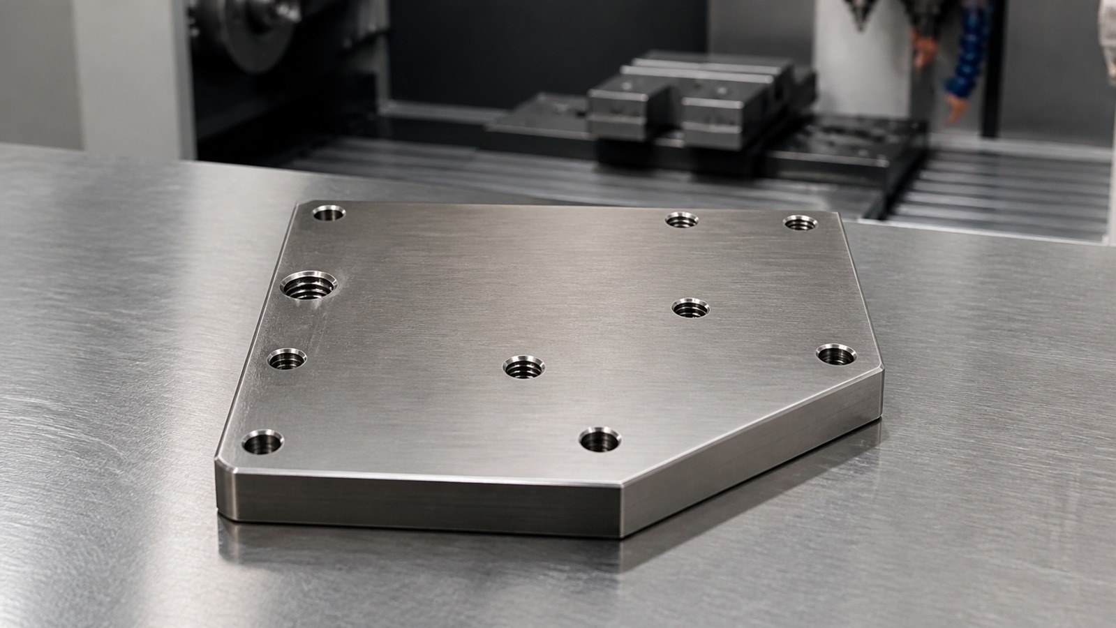
Engineer Wu (吴工) reviewed a sanitized machining case for a SUS 304 mounting plate. Based on the straight and angled edges, through holes, through-threaded holes, datum surface, surface texture, cleaning, and sealed packaging notes, Engineer Wu classified it as a mounting component for semiconductor automated inspection equipment. OEMACHwould manage its datum system, hole relationships, thread condition, deburring, surface protection, and delivery controls as one process chain.
Visible Drawing Data
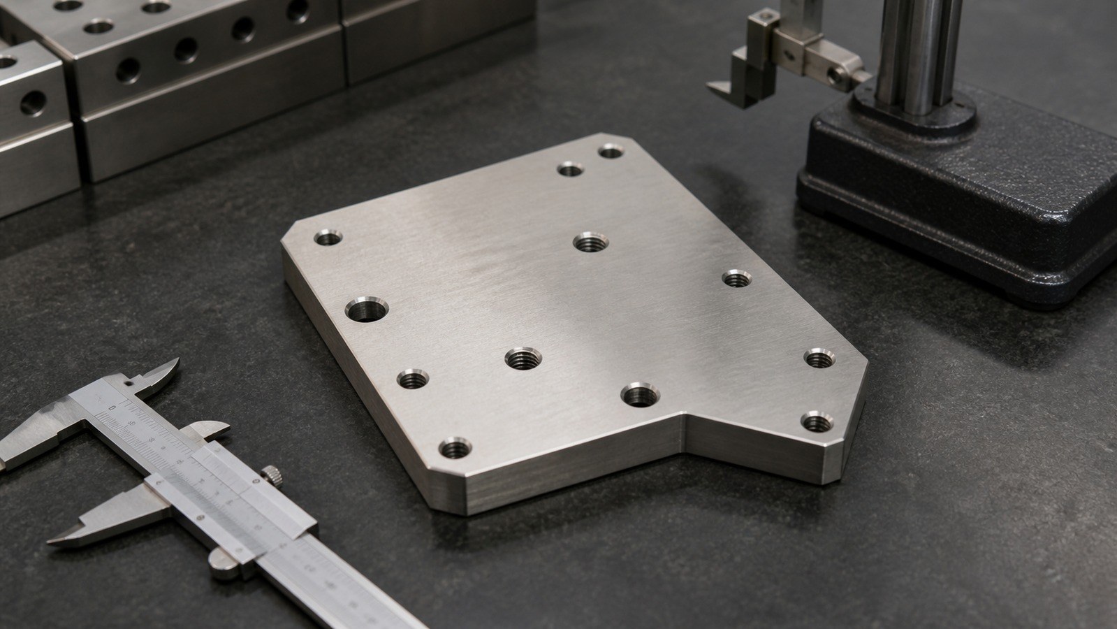
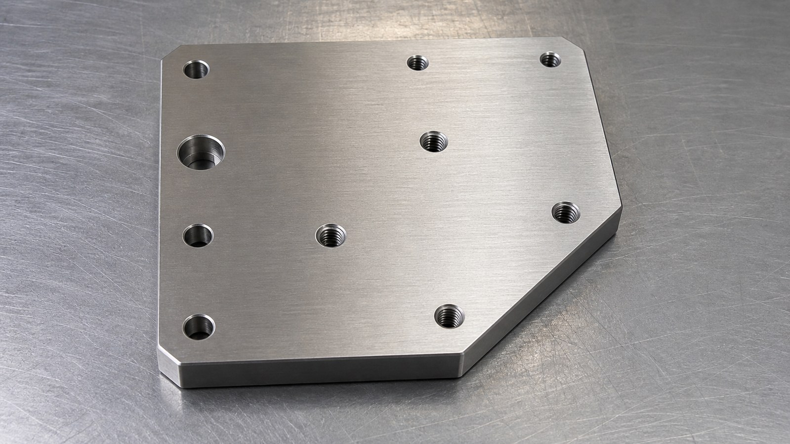
The component uses SUS 304 and has an envelope of 165 mm by 165 mm, a 100 mm bottom edge, a 15 mm thickness, and a 45° angled profile. Visible dimensions include 57 mm, 45 mm, and 56.5 mm hole-center distances, 38.25 mm and 76.5 mm angled dimensions, and a 15 mm edge distance. [Source: Customer-provided visible engineering drawing annotations]
The hole system includes five Φ9 through holes, three C10 features, one M16 through-threaded hole, and four M10 through-threaded holes. Primary surfaces are marked Ra 3.2, with Ra 6.3 for other surfaces. [Source: Customer-provided visible engineering drawing annotations]
Application Assessment
Engineer Wu considers the part a mounting plate for a detection mechanism, sensor bracket, or inspection-module support. This is a sanitized engineering assessment rather than confirmation of an actual customer machine. The hole system, angled profile, installation face, and thread directions should therefore be reviewed as related functional features.
Key Machining Risks
Engineer Wu identified stainless-steel work hardening, heat generation, hole-position accumulation, burrs at through-hole exits, thread continuity, fixture marks, and contamination after cleaning. Geometrical relationships should be interpreted using the defined datum system and functional orientation. [Source: ISO 1101:2017]
Process Recommendations
Engineer Wu proposed drawing review, datum confirmation, stock inspection, face preparation, profile roughing, hole machining, through-thread machining, angled-profile finishing, controlled deburring, surface review, alcohol cleaning, separated protection, cushioning, and vacuum sealing.
Engineer Wu would machine the key hole system from one installation-oriented coordinate system. General tolerances apply within their stated scope, while individually toleranced features remain controlled by their own callouts. [Source: ISO 2768-1:1989]
Delivery and Communication
For a small batch, Engineer Wu recommends confirming the controlled drawing, quantity, mounting datum, thread direction, cosmetic surfaces, cleaning method, sealed packaging, and sample-validation stage. OEMACHcan organize first-article confirmation records, dimensional review records, process check records, and project confirmation materials around the agreed scope.
FAQ
#### Why is this considered a semiconductor inspection-equipment mounting plate?
Engineer Wu bases the assessment on its SUS 304 plate geometry, through holes, through threads, angled profile, surface requirements, and clean sealed packaging notes.
#### What is the main stainless-steel machining concern?
Engineer Wu focuses on heat, chip evacuation, tool condition, work hardening, and burr formation at feature exits.
#### How should the hole system be controlled?
Engineer Wu recommends one datum-oriented coordinate system and staged review of center distances, edge distances, and angled-profile relationships. [Source: ISO 286-1:2010]
#### How are the surface texture requirements handled?
Engineer Wu separates primary surfaces from other surfaces and confirms the machining direction and review location. [Source: ISO 21920-1:2021]
#### Why is sealed packaging relevant?
Engineer Wu uses clean cushioning and separated contact protection to reduce scratching, impact, dust, and secondary contamination during delivery.
中文TDK
**Title:** 半导体自动化检测设备板类安装件加工|孔系、螺纹与毛刺控制
**Description:** 吴工结合SUS 304板类安装件图纸数据,复盘半导体自动化检测设备零件加工中的安装基准、贯穿孔、螺纹、斜边轮廓、表面纹理、清洁与密封包装。
**Keywords:** 半导体设备零件加工,自动化检测设备零件加工,SUS 304精密加工,板类安装件加工,精密孔位加工,贯穿螺纹加工,小批量零件加工
Scan to contact us
Contact: Allen
Email: shiziqiu@oemach.com
My whatsapp code