
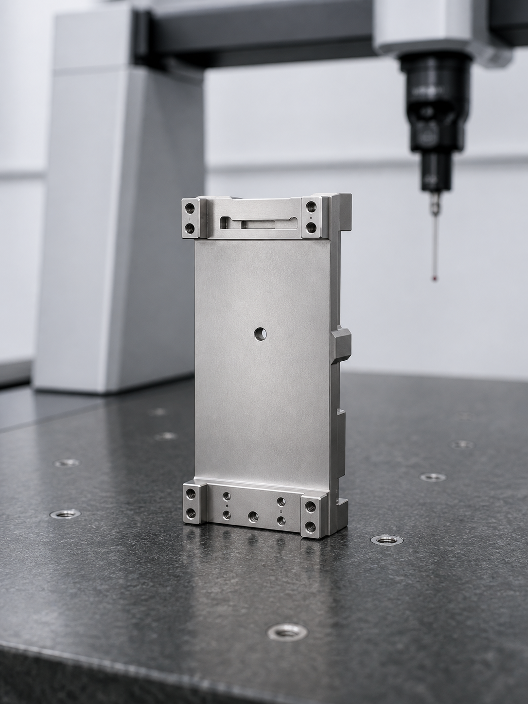
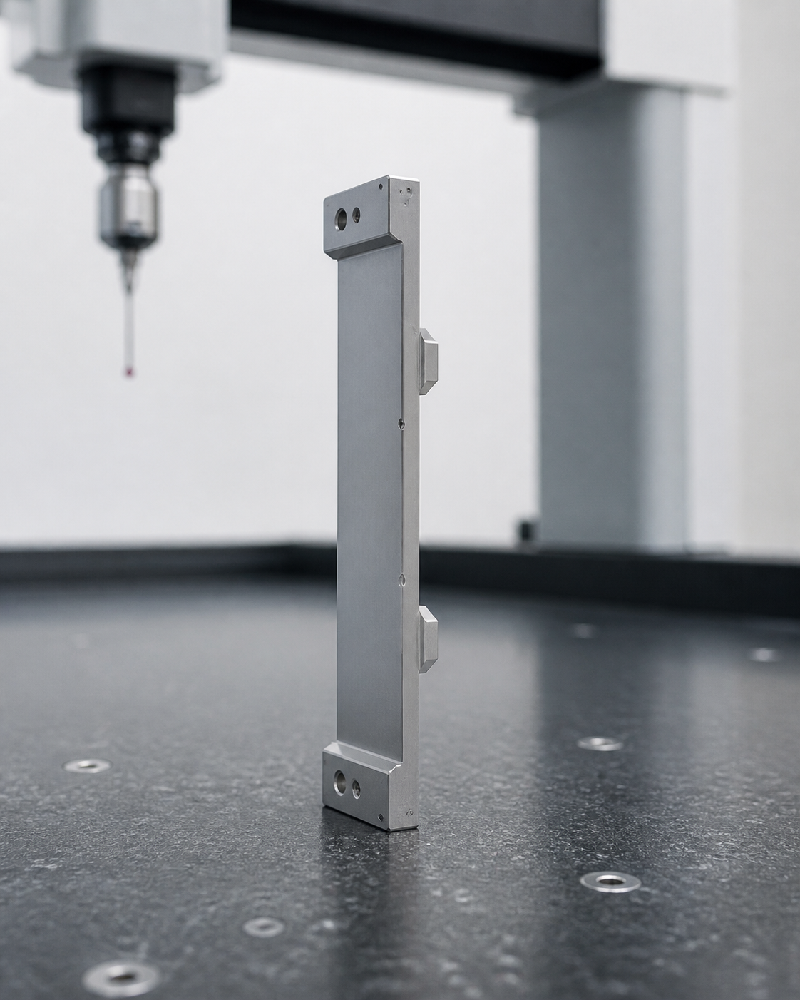
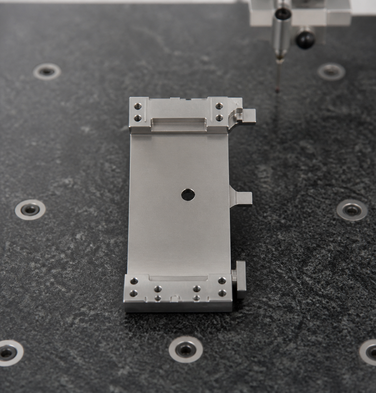
This anonymized engineering case study describes a proposed manufacturing and inspection route for a thin stainless steel alignment frame used in medical imaging or diagnostic equipment. The component is a tall rectangular plate with reinforced mounting blocks at both ends, several small precision holes, stepped ledges, side locating tabs and a central reference hole. Its shape appears straightforward, but the combination of a broad thin wall, narrow edge features and multiple related mounting points creates significant risks for distortion, datum transfer and inspection.
The application described here is an engineering interpretation based on the supplied drawing. The part is treated as a non-implant, non-patient-contact equipment component. Final material, tolerance, cleaning, traceability and validation requirements must be defined by the customer according to the actual device and regulatory environment.
Project Background and Functional Context
The frame was evaluated as a support and alignment component for a detector, imaging panel or calibration module. The large central plate provides a stable reference surface, while the top and bottom mounting blocks connect the frame to the surrounding equipment structure. Small holes may be used for fasteners, locating pins or adjustment hardware. Side tabs can establish lateral position or interface with covers, guides and cable-management elements.
For a medical imaging assembly, repeatability depends on the relationship between these features. A mounting hole can be within its individual size tolerance while still producing assembly error if its position relative to the primary datum is incorrect. Likewise, a flat plate may become slightly bowed after machining, causing the detector or calibration module to sit unevenly. The manufacturing plan therefore needs to control the complete datum system rather than treating every feature independently.
The engineering review focused on plate flatness, parallelism between the end mounting blocks, positional accuracy of the small holes, side-tab location, edge quality and a practical inspection method. The customer was advised to identify the true assembly datum, any surfaces that contact optical or electronic modules, and any edges close to cables or seals.
Drawing Review and DFM Decisions
Before quotation, the 2D drawing should be reviewed together with a controlled 3D model. The drawing defines tolerances, datum references, geometric controls, surface texture and inspection requirements. The model clarifies the stepped ledges, local thickness changes and small side features. Any discrepancy between the two files must be resolved before programming.
The likely critical characteristics include flatness of the main plate, parallelism and spacing of the reinforced end blocks, position of the central reference hole, locations of the small mounting holes, perpendicularity of side faces and the height of the side locating tabs. If the frame supports an imaging detector, the functional surface may require a tighter relationship to the mounting pattern than the general profile.
Several questions should be answered during DFM review. Are the small holes threaded, reamed or clearance features? Which holes establish location and which only provide clamping? Is the central hole functional or used for assembly access? Are the tabs true locating surfaces? Does the plate operate in a free state or is it restrained by the assembly? Is passivation required after machining? These answers influence tool selection, setup strategy, inspection and cost.
Internal transitions should use practical radii wherever function permits. A controlled radius allows a stronger cutter and reduces stress concentration. Edge-break requirements should also be explicit. A general deburring instruction may not adequately protect nearby cables, seals or technician-access areas.
Proposed 316L Stainless Steel Material
For this case, 316L stainless steel was proposed because it offers useful corrosion resistance for medical, laboratory and cleaning-intensive equipment. It can also be passivated when required by the purchasing specification. The material selection does not itself establish compliance with a medical standard; the customer remains responsible for specifying the material condition, certification, cleanliness and validation appropriate to the final equipment.
316L requires disciplined machining. It can work-harden when a tool rubs, and it tends to produce persistent burrs around small holes and thin edges. Sharp carbide tooling, consistent feed, controlled engagement, effective coolant delivery and reliable chip evacuation help maintain surface quality. Tool wear must be monitored because rising cutting force can push the thin plate and change flatness.
CNC Manufacturing Process
The proposed route begins with certified plate or a near-net rectangular blank. Material identity is checked before release. The blank is stress-aware saw cut with additional stock, then lightly faced on both sides to establish parallel reference surfaces without removing excessive material from one face.
In the first main setup, the primary mounting face and two reference edges are established. The top and bottom mounting areas are rough machined using balanced toolpaths. Material is removed in alternating regions so that heat and residual stress are not concentrated at one end. Small holes are initially prepared where this supports later datum transfer, while critical finished holes remain undersize.
The central plate, stepped ledges and side tabs are rough machined with uniform finishing stock. Heavy roughing is completed before the thin sections reach final thickness. This preserves stiffness and reduces the risk that cutting force will deflect the part. The frame may then be released, allowed to stabilize and checked for movement before finishing.
The second setup locates from the established datum system using soft jaws, vacuum support or a dedicated fixture selected according to the final thickness and surface requirements. Clamping pressure is distributed across stable areas. The fixture must support the plate without forcing it flat, because a restrained part can appear correct during machining and spring into a bowed condition after release.
Final facing passes bring the broad surfaces to size. The reinforced end blocks, ledges and tabs are finish milled with controlled cutter engagement. Critical holes are drilled, reamed, bored or thread milled according to the specification. Positional features are produced from the same datum system so that the top and bottom mounting patterns remain related.
Distortion and Burr Control
Distortion is the primary manufacturing risk. Uneven stock removal, excessive clamping, heat buildup and residual stress can all move the plate. The process uses symmetric machining where possible, conservative finishing cuts and repeated free-state checks. If inspection shows movement after roughing, an intermediate stabilization step can be introduced before final sizing.
Toolpaths should avoid long dwell periods and abrupt changes in engagement. A sharp face mill or end mill with suitable geometry reduces cutting pressure. Final passes are performed with consistent direction and load, and tool offsets are adjusted from measured results rather than nominal assumptions.
Deburring is completed under magnification where necessary. The small holes, side tabs and step intersections are checked from several directions because stainless steel can leave thin burrs that are difficult to see. Functional edges receive the specified break without rounding datum faces or changing tab width. Abrasive media are controlled so that residue does not remain inside small holes.
CMM Inspection Strategy
Inspection begins from the drawing datum system. A coordinate measuring machine can verify flatness of the main surface, parallelism and spacing of the end blocks, hole positions, central-hole location, tab profile and selected step heights. The program should not create a convenient coordinate system that differs from the functional assembly reference.
Flatness is checked in a free state unless the drawing specifies restraint. The end mounting areas are measured at multiple points to identify local tilt or twist. Hole positions are evaluated together as a pattern, and any locating holes receive the specified size and form checks. Side tabs are measured relative to the primary plane and longitudinal datum because their relationship may control lateral assembly position.
For prototypes or first-article production, a complete dimensional report can be supplied when requested. Production lots may follow an agreed sampling plan, while critical alignment features receive the inspection frequency specified by the customer. Material certificates, inspection records and lot identity can be connected through the job traveler when traceability is required.
Cleaning, Passivation and Packaging
After machining and inspection, the frame is cleaned to remove coolant, chips and handling residue. The cleaning process must be compatible with the required surface condition and any subsequent treatment. If passivation is required, the applicable standard, acceptance criteria and documentation should be defined on the drawing or purchase order.
The finished part is dried and visually inspected under suitable lighting. Packaging prevents metal-to-metal contact and protects the broad datum surface from dents or scratches. Clean bags, separators or compartmented trays can be selected according to quantity and cleanliness expectations. Packaging material should not leave fibers or adhesive residue on functional surfaces.
Engineering Outcome
The proposed process links machining, workholding and inspection to the functional datum system from the beginning. Balanced stock removal and controlled clamping reduce the risk of plate distortion. Producing related holes from a common datum improves repeatable assembly, while dedicated deburring and cleaning steps protect nearby cables, seals and sensitive equipment modules. CMM inspection provides evidence that the full alignment pattern works as a system rather than as a collection of isolated dimensions.
This case demonstrates why thin medical-equipment frames benefit from early supplier review. A clear drawing, controlled 3D model and agreed inspection plan allow manufacturing decisions to be resolved before material is cut. That reduces interpretation risk, supports a faster first-article review and gives the customer useful dimensional data for assembly validation.
Information to Include in a Similar RFQ
For an effective review, provide the 2D drawing and 3D model, material grade and condition, quantity, critical tolerances, datum scheme, surface finish, edge requirements, cleaning or passivation expectations, inspection-report format, certification and traceability needs, packaging method and delivery target. Explaining which holes and surfaces establish detector alignment is especially valuable when the supplier is evaluating manufacturability.
If you have parts machining requirements, please contact me: tanghangyun@oemach
