
A case study on machining a TC4 titanium long ankle link with polished finish, hot-fit bearing bores, center-distance control and protected delivery.
A long ankle link for a humanoid robot may look simple from the outside, but it is a motion-chain part. It connects joint elements, transmits swing load and carries bearing installation at both ends. The real challenge is not only machining the outline, but keeping the titanium cutting process, hot-fit bearing bores and long center-distance relationship stable.
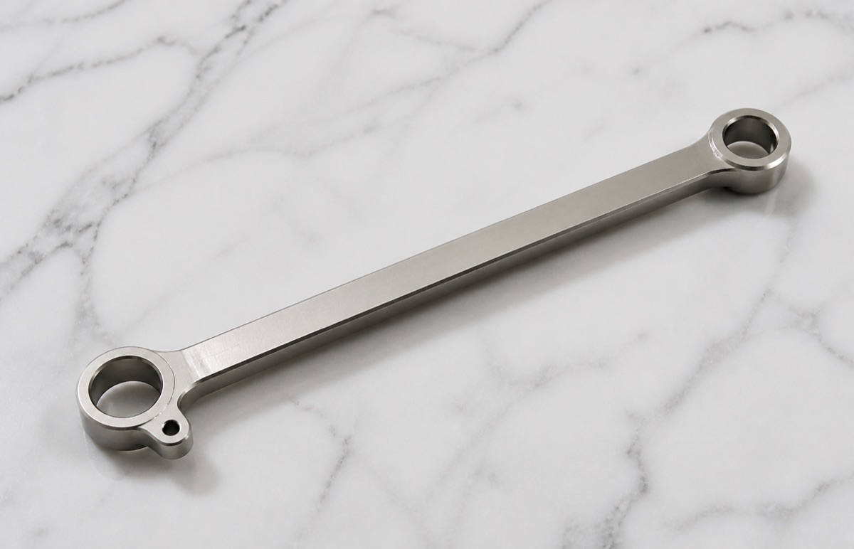
This case covers a TC4 titanium ankle link with a slender body, circular bearing structures at both ends, a small hole and local ear near one end, and a polished delivery finish. OEMach treated the part as a slender titanium connecting link with press-fit or hot-fit bearing features rather than as a simple milled profile.
Project Snapshot
| Item | Project detail |
|---|---|
| Part type | Long ankle link for a humanoid robot ankle joint |
| Material | TC4 titanium alloy |
| Structure | Slender bar body, bearing bores at both ends, local small hole, end ring features and polished surfaces |
| Finish | Polished metallic finish, with bore mouths and contact areas protected during finishing |
| Process focus | Titanium cutting stability, hot-fit bearing bore control, center distance, slender-part deformation and burr control |
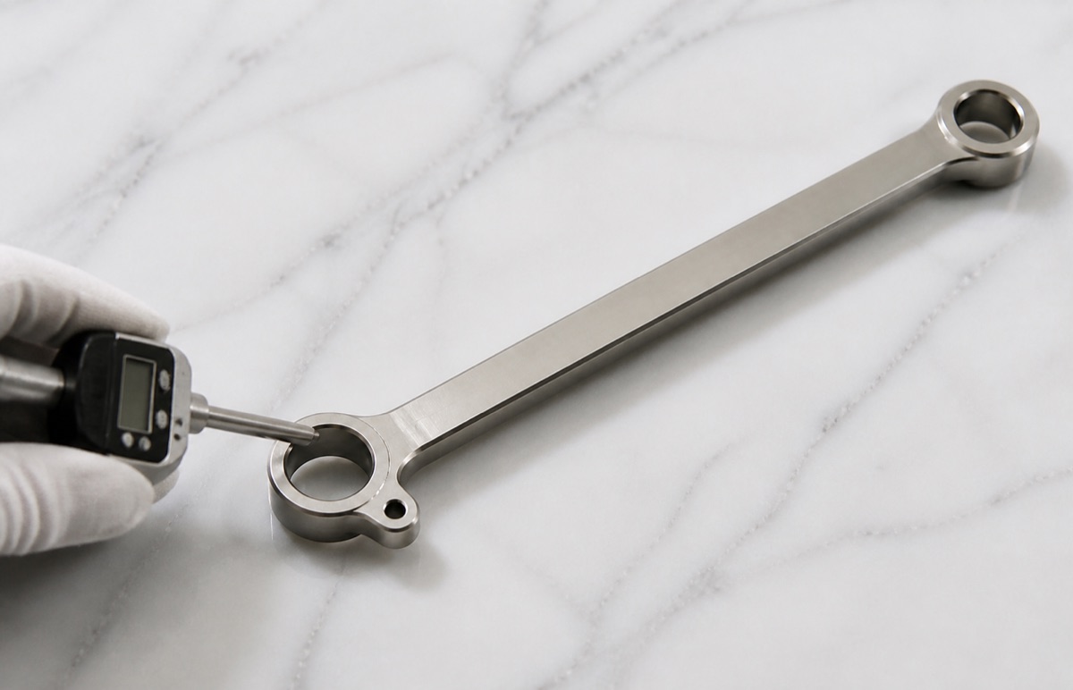
| Inspection focus | Bore size, roundness, bore-wall condition, bore-mouth chamfer, center distance, straightness and polished appearance |
Why TC4 Titanium Changes the Machining Logic
TC4 titanium has low thermal conductivity and high tool load compared with many aluminum parts. Cutting heat stays near the tool and bore wall, so tool wear, cutting parameters and coolant strategy directly affect bore quality and dimensional stability.
For a hot-fit bearing bore, diameter alone is not enough. Roundness, bore-wall roughness, chamfer size and the absence of small burrs all influence whether the bearing seats smoothly without skewing or scratching the bore mouth.
The slender body adds another layer of risk. After roughing releases stock, a long link can move slightly. If the relationship between the two end bores shifts, each bore may still measure well in isolation while the whole link no longer matches the ankle mechanism geometry.
Machining Challenges
The first challenge is heat and tool wear in TC4 titanium. Stable step-by-step bore machining is needed so the bore wall does not show heat damage, tearing or taper from a worn tool.
The second challenge is long-distance center control. The two bearing bores define the motion axis relationship, so datum planning must protect the center distance across roughing, semi-finishing, finishing and inspection.
The third challenge is polishing. Polishing changes surface state and can damage carefully controlled bore mouths if they are not protected. For this reason, critical bores and inner walls should be checked before and after finishing.
OEMach Manufacturing Solution
OEMach first planned the datum relationship between the two bearing bores and the link centerline. Rough machining retained balanced stock to reduce bending from one-time heavy removal. After semi-finishing, release or rechecking steps can help identify stress movement before final finishing.
The bearing bores were machined with a stable tool path and controlled chamfer strategy. The chamfer had to support assembly without reducing the effective press-fit contact too much. The small hole near the end ring was kept in the same datum logic to reduce accumulated positioning error.
Before polishing, bore mouths and inner walls were protected and reviewed. After polishing, key bores, center distance and visible surfaces were rechecked so the part could move directly into prototype assembly validation.
Inspection and Delivery Control
Inspection should not stop at one bore diameter. First-article review should cover both bearing bores, roundness, bore-wall condition, bore-mouth chamfer, the local small hole, body thickness, overall straightness and center distance.
For hot-fit or press-fit applications, using the actual bearing or a representative gauge can help confirm installation feel. During small-batch work, tool life, bore machining cycle and post-polish inspection should stay in the process record.
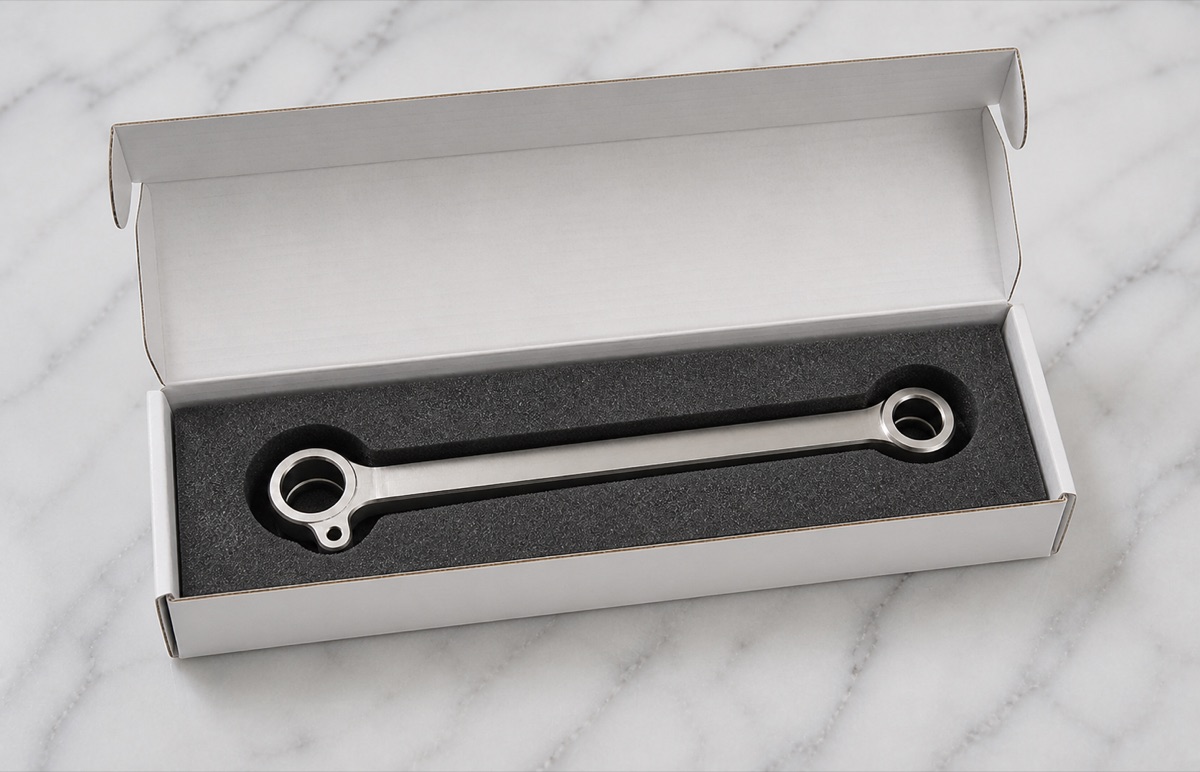
For delivery, a polished titanium long link should not be packed loose. Form-fit foam keeps both end rings and the polished body separated from impact or rubbing, protecting bore mouths and appearance surfaces before customer assembly.
FAQ
Why is a TC4 ankle link harder to machine than an aluminum link?
TC4 titanium conducts heat slowly and loads the cutting tool more heavily, so bore-wall quality, tool wear and dimensional stability require closer process control.
What matters most for a hot-fit bearing bore?
Bore diameter, roundness, bore-mouth chamfer, bore-wall condition and cleanliness should be controlled together. One size value is not enough.
Why does polishing need extra inspection?
Polishing can change edge condition and visible surface state. Critical bores and bore mouths should be protected and rechecked after polishing.
Why is center distance important on a long ankle link?
The center distance between the two bearing bores affects the ankle mechanism geometry. If that relationship drifts, the joint may not assemble or move consistently.
Ready to get a quote for your CNC machined parts?
Submit your engineering drawings to qiancj@oemach.com. We support prototype sampling and small-batch production with strict tolerance control.