
If you have parts machining requirements, please contact me: tanghangyun@oemach
Summary
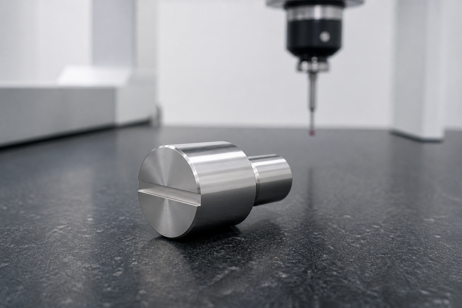
This anonymized engineering case explains a proposed manufacturing and inspection route for a compact 316L stainless steel locating pin used in medical equipment assembly, calibration or test fixtures. The part combines a stepped cylindrical body, a smaller locating shaft, controlled shoulders, edge breaks and a straight drive slot. Although the geometry appears simple, the relationship between concentric diameters, shoulder position, slot orientation, burr control, cleanliness and inspection setup can directly affect repeatable assembly. OEMach reviewed the part as a precision turned component requiring stable datum transfer, controlled secondary milling and documented final inspection.
Project Background and Functional Context
The inquiry was evaluated as a small medical-equipment positioning component rather than an implant or a patient-contact product. A part of this type may be used to locate a removable module, establish a repeatable reference in an imaging accessory, retain an adjustment mechanism, or support calibration and test equipment. The exact end use remains controlled by the customer; the application described here is an anonymized engineering interpretation based on the visible geometry.
The functional concept is straightforward. The small shaft enters a mating bore, the larger cylindrical head establishes a stop, and the straight slot allows controlled installation or removal with a suitable tool. In practice, however, reliable performance depends on more than the nominal diameters. The locating shaft must remain concentric with the head, the shoulder must be square enough to seat consistently, the end faces must not carry raised burrs, and the slot must not distort the surrounding circular profile.
For medical-equipment sourcing, the drawing package should identify the material grade, applicable material condition, critical dimensions, tolerance scheme, surface texture, edge requirements, cleaning expectations, inspection records, lot traceability and packaging method. If the part is used near a sterile field or in a regulated assembly, the customer should also define any additional validation, passivation, biocompatibility or cleanliness requirements rather than relying on a generic “medical grade” note.
Material and Drawing Review
316L stainless steel was selected for this case because it offers useful corrosion resistance and is widely considered for medical and laboratory equipment components. The final material decision must still reflect the actual operating environment, cleaning agents, contact conditions and regulatory obligations. Material certification can be requested when heat or lot traceability is part of the purchasing specification.
Before quotation, the engineering review separates functional characteristics from general dimensions. The likely critical features are the locating-shaft diameter, the relationship between the shaft and large head, the axial position and squareness of the shoulder, overall working length, slot width and depth, end-face condition and edge treatment. The mating bore and assembly method are equally important. A diameter tolerance that appears achievable in isolation may still create assembly variation if form, runout or shoulder alignment is not addressed.
The original drawing is therefore reviewed together with the 3D model whenever available. Any conflict between the model and controlled 2D drawing must be resolved before manufacturing. Unspecified radii, ambiguous slot-bottom geometry, sharp-edge notes and surface-finish callouts should be clarified early. This prevents the machinist from making assumptions that may alter tool engagement, seating behavior or cleanability.
Key Manufacturing Risks
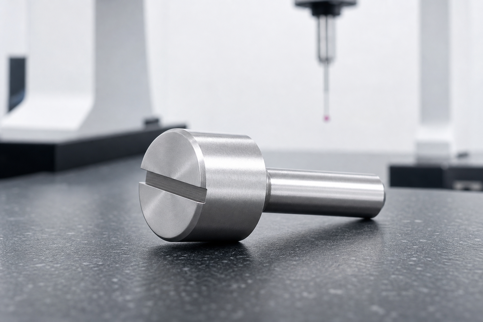
The first risk is datum continuity. Most cylindrical features can be produced efficiently in one turning setup, but the slot requires a secondary operation. If the part is re-clamped on a finished functional diameter without a controlled fixture, marking and angular error may be introduced. A split collet or soft-jaw fixture should support the part without distorting or scratching the locating surface.
The second risk is stainless-steel process behavior. 316L can generate heat, work harden and produce persistent burrs when tools are dull, feeds are unstable or cutting engagement is allowed to rub. Tool condition, chip evacuation, coolant delivery and a consistent cutting strategy matter, especially on the small shaft and at the shoulder transition.
The third risk is slot quality. Milling the straight slot creates two long edges and terminal features that can retain small burrs. Aggressive manual deburring can round the end face, widen the slot or change its visual symmetry. Edge finishing should remove loose and raised material while preserving the controlled geometry.
The fourth risk is inspection access. A short stepped component may be difficult to hold consistently if the inspection fixture contacts the same surface being measured. The inspection plan needs a repeatable seating method, a defined primary axis and sufficient access for the probe or optical system. Measurement uncertainty should be appropriate for the tolerances being reported.
Recommended CNC Machining Route
The proposed route begins with review of the controlled drawing, model, quantity, material documentation and inspection requirements. Bar stock is checked for size and condition before cutting. The main turning operation then establishes the part axis and produces the large head, smaller shaft, shoulders, end faces and required chamfers with as many functional relationships held in one setup as practical.
Toolpaths should avoid unnecessary dwell on the stainless-steel surface. Roughing leaves a controlled finishing allowance, followed by a stable finish pass for the locating diameter and shoulder. In-process checks monitor tool wear before it affects the full batch. If the drawing includes a narrow transition relief or specific corner radius, the selected insert and tool nose must reproduce that geometry without leaving a stress-raising notch.
After turning, the part transfers to a dedicated fixture for slot milling. The fixture references a non-damaging cylindrical surface and controls axial position. Slot width and depth are produced with a suitable end mill or slotting strategy, with cutting parameters chosen to limit chatter and exit burrs. For small batches, the first piece is checked before the remaining quantity proceeds.
Deburring is treated as a controlled operation. Technicians inspect the slot edges, shaft end, shoulder and chamfers under magnification when necessary. The goal is a clean, safe edge without uncontrolled rounding. Parts are then cleaned to remove chips, coolant and polishing residue. If passivation is required, its specification, acceptance criteria and documentation should be stated by the customer before processing.
Dimensional Inspection and CMM Strategy
Inspection starts with identification of the functional datum structure. The axis of the locating shaft can serve as a primary reference for concentric features, while an appropriate shoulder or end face establishes axial position. The plan may combine calibrated micrometers, bore or snap gauges, an optical system and a coordinate measuring machine. The method depends on tolerance, feature accessibility, batch size and reporting needs.
The locating diameter is checked for size at more than one axial position when form is relevant. The relationship between the small shaft and large head is evaluated for runout or coaxiality according to the drawing requirement. Shoulder position, overall length and face orientation are measured from the defined datum, not from an arbitrary handling surface. Slot width and depth are checked with an appropriate contact or optical method, and the slot is visually examined for remaining burrs or edge damage.
For an inspection report, the customer should specify whether a standard dimensional report, first article inspection, CMM report, material certificate or lot-level sampling record is required. Not every feature needs a CMM result, but every critical characteristic should have a suitable method and acceptance rule. A clear ballooned drawing can align purchasing, manufacturing and quality teams before production begins.
Cleaning, Handling and Delivery
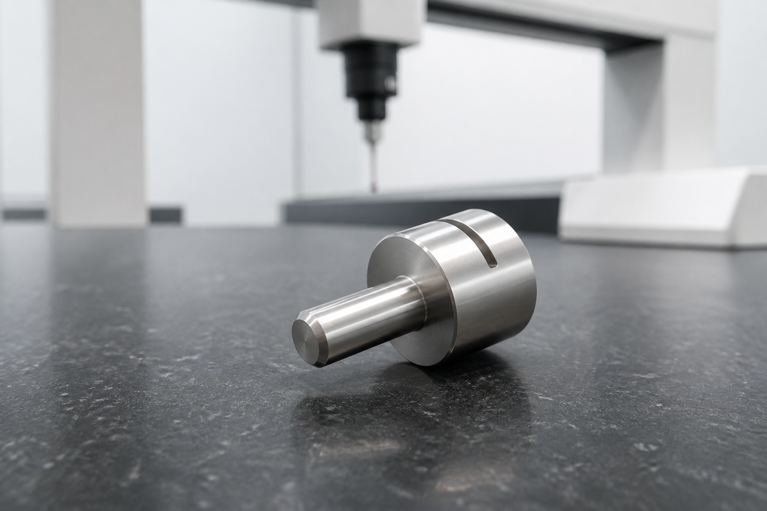
Small precision stainless-steel parts can pass dimensional inspection and still arrive with cosmetic or functional damage if packaging is treated as an afterthought. Finished locating surfaces should not rub against other parts during transport. Individual cavities, clean sleeves or separated trays can protect the shaft, shoulder and slot edges. Packaging materials should not shed fibers or leave residues that conflict with the customer’s cleaning process.
The packing plan should identify the part revision, quantity and lot where traceability is requested. Inspection documents and material certificates should match the shipped batch. For a medical-equipment customer, OEMach would also confirm whether the parts are supplied as standard cleaned industrial components or must meet a customer-defined validated cleaning and packaging procedure. The machining supplier should not imply sterility unless sterilization and sterile-barrier requirements are explicitly included and controlled.
Result and Sourcing Lessons
This review shows why a compact turned pin deserves a complete manufacturing plan. The lowest-risk route keeps concentric features in one turning setup, uses a protective fixture for slot milling, controls deburring, and defines inspection from functional datums. The component’s apparent simplicity should not hide the importance of mating-fit information, edge quality, cleanliness and documentation.
For an efficient RFQ, buyers should provide the STEP or STP model, controlled 2D drawing, required 316L specification, quantity, critical tolerances, surface-finish requirements, cleaning or passivation notes, inspection-report expectations and target delivery date. Details about the mating bore, installation tool and assembly environment help the engineering team identify tolerance risks before quotation.
FAQ
Why use both a 3D model and a 2D drawing? The model communicates geometry efficiently, while the controlled drawing defines tolerances, datums, surface texture, edge notes, material requirements and inspection expectations.
Can the entire part be completed by CNC turning? Most cylindrical geometry can be turned, but the straight end slot normally requires a secondary milling operation or a suitably equipped turn-mill process.
Why is slot deburring important? Residual burrs can interfere with tooling, handling, cleaning and assembly. Excessive deburring can also change slot width or round a functional edge, so the operation must be controlled.
Is 316L automatically suitable for every medical application? No. Suitability depends on the equipment environment, cleaning chemistry, contact conditions, regulatory requirements and the customer’s approved material specification.
What inspection information should be included in the RFQ? Identify critical features, datum references, required report format, sampling level, material certification, first-article requirements and any special traceability expectations.
Can OEMach support prototypes and small batches? OEMach supports prototype and small-batch precision manufacturing. The final process, inspection scope and lead time are confirmed after review of the drawing package and project requirements.