
A humanoid robot motor clamp is not just a curved bracket. It must wrap around the outer diameter of a joint motor or motor housing with stable contact while keeping end hole groups, threaded holes and black anodized appearance consistent.
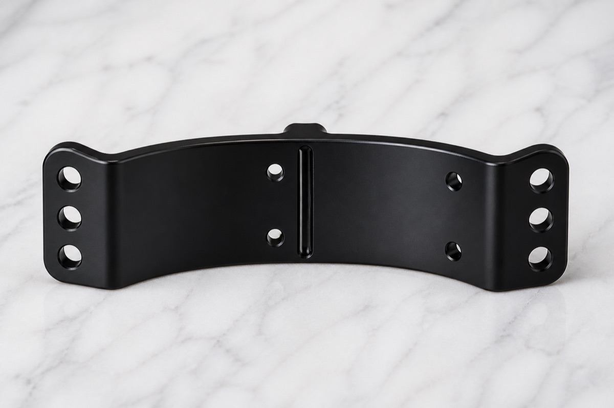
This case covers a 6061-T6 aluminum motor clamp used around a humanoid robot joint motor. The part has a curved thin-wall body, mounting ears at both ends, a narrow center slot, small holes and end hole groups for fastening or locating against adjacent brackets. OEMach managed the project around the curved datum, hole-group relationship and post-anodizing inspection.
Project Snapshot
| Item | Project detail |
|---|---|
| Part type | Curved motor clamp for humanoid robot joint motor or motor housing fixation |
| Material | 6061-T6 aluminum |
| Structure | Curved thin-wall body, end mounting ears, end hole groups, threaded holes, narrow center slot and small holes |
| Finish | Black anodizing |
| Process focus | Curved support datum, thin-wall deformation, hole-group position, thread quality, deburring and anodizing preparation |
| Inspection focus | Curved profile, end hole groups, hole diameter, thread go/no-go, slot width, end-face flatness and black surface condition |
Why the Curved Profile Matters
The value of this clamp is not only whether it looks curved. During assembly, it must fit the motor outside diameter or neighboring round structure without forcing the end holes into stress. If the curved profile springs back or the end ears shift, the hole group may still measure correctly on the bench but fasten unevenly on the motor.
The end hole groups define screw locking and positioning. Hole diameter, hole pitch and chamfer must stay stable so the customer does not feel tight screw starting, hole misalignment or uneven clamping pressure during installation.
Machining Challenges
The first challenge is thin-wall rigidity. The curved section is not thick, so insufficient support during roughing and finishing can cause local springback. That may change the arc, end-face position and hole-group relationship after unclamping.
The second challenge is the narrow center slot and small holes. They release local stress and create more burr-sensitive edges. Burrs around holes and slots can become more visible after black anodizing and may also affect handling or assembly.
The third challenge is anodizing preparation. Black anodizing can magnify scratches, clamping marks, burr shadows and cleaning residue. Deburring should therefore be planned from tool path, clamping, hole-mouth chamfer and pre-anodizing inspection, not treated as a quick final clean-up.
OEMach Manufacturing Solution
OEMach first established a stable curved outside reference and end-ear datum. Conformal support or soft fixtures were used to reduce deformation in the thin-wall region. Roughing retained controlled allowance, and finishing was done after the datum and clamping state were stable.
For through holes and threaded holes, hole-mouth chamfers were controlled according to fastening needs. The goal was to improve screw-starting feel without cutting away the effective contact area of the end mounting ears.
Before black anodizing, all-around deburring and cleaning were completed. After anodizing, OEMach rechecked hole mouths, curved surfaces, end ears and visible faces to confirm that the part was ready for assembly and visually consistent as a black component.
Inspection and Delivery Control
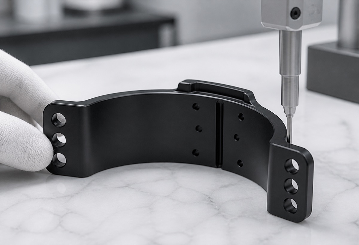
Inspection looked at the curved contour, end hole-group position, hole diameter, thread go/no-go, narrow slot width, end-face flatness and black surface appearance as one functional set. Checking only a single hole diameter is not enough for a curved clamp that must seat around a motor housing.
For first-article review, CMM, optical projection or dedicated gauges can confirm the curved profile and hole-group relationship. For small batches, sampling should include hole groups, threads, appearance and post-anodizing condition. Before packaging, holes should be free of chips and anodizing particles.
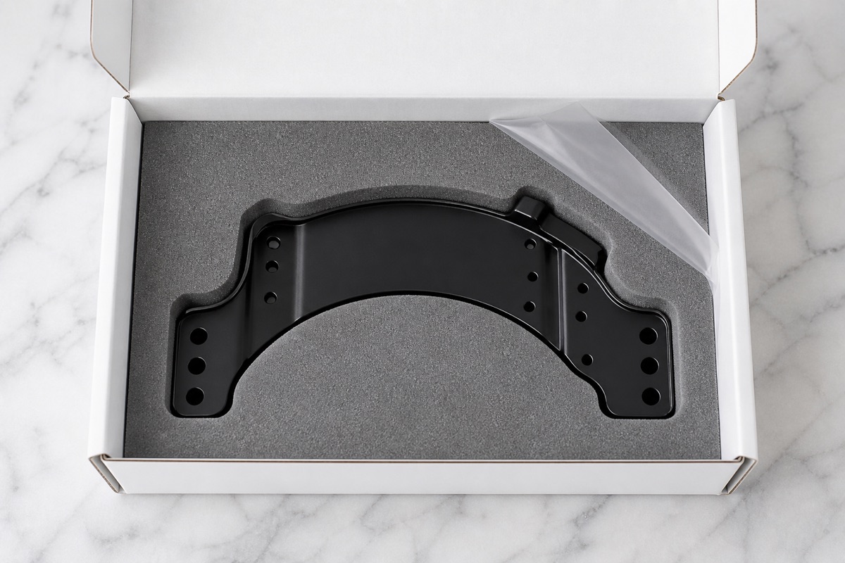
For delivery, OEMach used single-piece form-fit foam positioning. The end ears and curved visible surfaces were separated from friction, helping the customer open the package, inspect the contour, confirm clean hole mouths and move directly into assembly validation.
FAQ
Why is the curved profile critical in motor clamp machining?
The curved profile affects contact with the motor outside diameter or adjacent round structure. Profile error can make the hole group load unevenly during fastening.
Why inspect appearance before black anodizing?
Black anodizing makes scratches, burrs and clamping marks more visible. Pre-finish review reduces the risk of cosmetic rejection after treatment.
Can this type of motor clamp be made as a fast prototype?
Yes, but lead-time planning should include machining, deburring, anodizing, post-finish inspection and protected packaging, not only CNC cutting time.
Ready to get a quote for your CNC machined parts?
Submit your engineering drawings to qiancj@oemach.com. We support prototype sampling and small-batch production with strict tolerance control.