
The machining challenge of a PCB bracket is not the number of holes. For a humanoid robot waist PCB bracket, the thin plate, bend height, mounting hole position and black anodized appearance must all meet assembly requirements at the same time.
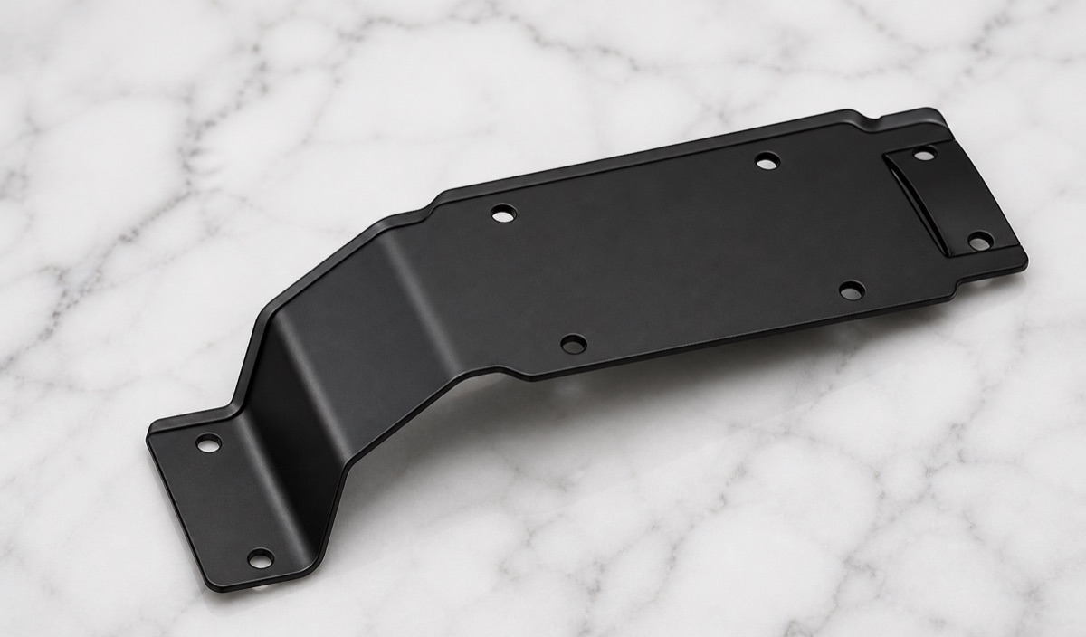
This case covers a 6061-T6 aluminum bracket with black anodizing. The structure is a long thin support plate with a bend or height offset at one end, multiple mounting holes, local reliefs, radiused transitions and small end platforms. It supports PCB or related modules in the waist area of a humanoid robot.
Project Snapshot
| Item | Project detail |
|---|---|
| Part type | Waist PCB mounting bracket for humanoid robot |
| Material | 6061-T6 aluminum |
| Structure | Long thin plate, bend-height offset, mounting holes, local reliefs, radius transition and end platforms |
| Finish | Black anodizing |
| Process focus | Hole datum, thin-plate flatness, bend height, radius transition, burrs and pre-anodizing appearance |
| Inspection focus | Mounting hole position, hole diameter, bend height, flatness, radius transition, small platforms and black surface condition |
Why the Bracket Can Fit but Still Sit Wrong
During customer assembly, three points matter most: whether the holes align, whether the bend height is correct and whether the mounting face stays flat. Hole position error affects PCB fastening, bend-height error affects clearance to surrounding structures, and poor flatness can stress the PCB.
The black anodized finish also means that burrs, scratches and pressure marks before finishing must be controlled early. After anodizing, small edge defects and color differences around bends can become more visible.
Machining Challenges
The first challenge is thin-plate deformation. Long sheet-like parts can warp slightly during machining, forming or clamping, and that affects final seating.
The second challenge is the bend height and radius transition. The bend area must reach the specified height while avoiding cracks, pressure marks or inconsistent finish around the radius.
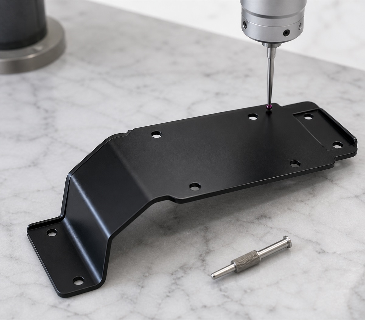
The third challenge is hole-position relationship. Multiple mounting holes run along the long side. If the datum is unstable, accumulated hole-distance error can affect PCB installation even when each hole diameter is acceptable.
OEMach Manufacturing Solution
OEMach first separated functional faces from cosmetic faces, then defined the hole datum and bend-height control method. During machining and forming, support and clamping were controlled so the thin plate was not locally pressed out of shape.
After forming, the relationship between mounting holes and bend height was checked rather than checking only single hole diameters. Hole-mouth chamfers, long-edge burrs, bend transition and surface scratches were reviewed before black anodizing.
After anodizing, OEMach rechecked visible surfaces, hole mouths, mounting face flatness and cleanliness. The goal was to let the bracket enter the customer's assembly validation without extra touch-up.
Inspection and Delivery Control
Inspection included mounting hole position, hole diameter, bend height, radius transition, long-plate flatness and small end platforms. For PCB brackets, hole position should be checked together with reference edge, bend face and hole-group relationship.
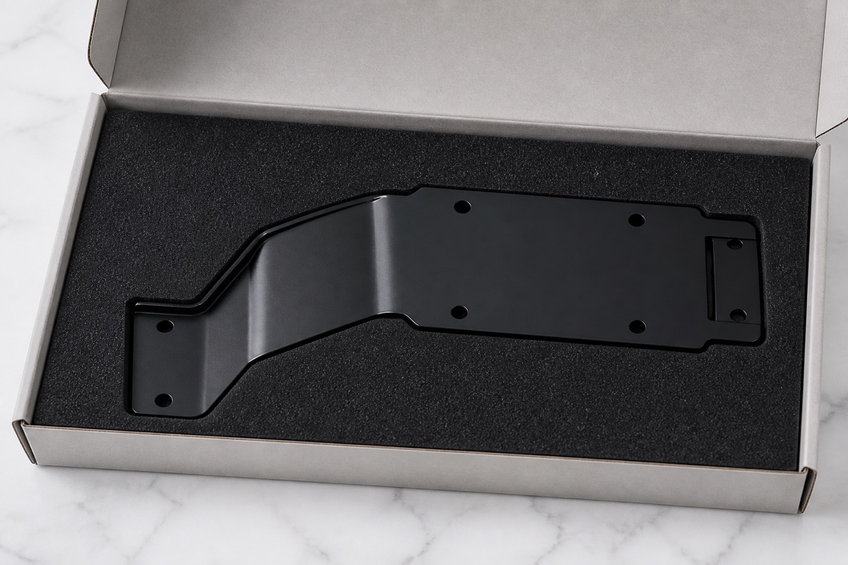
Post-anodizing review focused on bright edges around holes, edge dents, color change near the bend, surface scratches and cleanliness. Thin brackets can also bend during transport, so the packaging method is part of the quality plan.
OEMach used form-fit foam, end positioning and single-piece separation to protect the bend region and black surface. For a PCB mounting bracket, clear hole position, clean surface and no transport bending are the most direct delivery quality indicators.
FAQ
Why is bend height critical for a PCB bracket?
Bend height controls clearance between the PCB, harness, housing and neighboring structures. Error can cause interference or poor seating.
What should be checked before black anodizing?
Hole mouths, bend edges, cosmetic faces, burrs and surface marks should be reviewed because anodizing can make these defects more obvious.
How can a long thin bracket be protected during delivery?
Form-fit foam, end positioning and individual separation help prevent bending, rolling and surface rubbing.
Ready to get a quote for your CNC machined parts?
Submit your engineering drawings to qiancj@oemach.com. We support prototype sampling and small-batch production with strict tolerance control.