
A complex linkage part can pass single-hole inspection and still fail assembly. For a humanoid robot waist linkage assembly, the machining focus is not one isolated size; it is the unified datum relationship among the center flange, side connection arms and dual-side hole features.
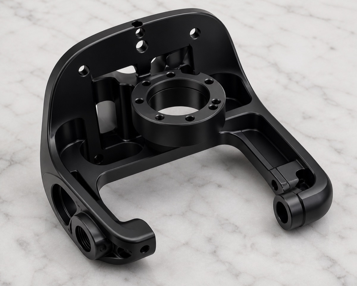
This case covers a 6061-T6 aluminum waist linkage assembly with black anodizing. The part includes a large rounded outer frame, center cylindrical flange, circular hole group, side lugs, dual-side threaded holes, weight-reduction cavities and ribs. OEMach managed the project as a complex robot structural component from DFM through post-anodizing reinspection.
Project Snapshot
| Item | Project detail |
|---|---|
| Part type | Waist linkage assembly for humanoid robot structure |
| Material | 6061-T6 aluminum |
| Structure | Center flange, circular hole group, side connection arms, dual-side threads, cavities and ribs |
| Finish | Black anodizing |
| Process focus | Unified datum, multi-face machining, thread verification, cavity deburring and pre-anodizing surface control |
| Inspection focus | Hole group position, perpendicularity, side holes, dual-side threads, rib/cavity roots and post-finish appearance |
Engineering Function and Risk
In the waist structure of a humanoid robot, this component supports connection, load transfer and assembly positioning. The center flange is the core fastening and locating area, while the side arms and threaded holes define how the part relates to neighboring modules.
If the center flange hole group, side holes and two-sided threads do not share a stable datum, the customer may experience difficult fastening, local interference or abnormal load distribution. Black anodizing adds another layer of control because scratches, burrs, cleaning residue and bright spots become more visible after finishing.
Machining Challenges
The first challenge is datum unification. The center bore, circular hole group, side holes and dual-side threads cannot be treated as unrelated features. If they are aligned independently, accumulated error can appear at assembly.
The second challenge is deformation during multi-face machining. Large cavities and ribs are useful for weight reduction, but roughing can release stress in local thin areas. Fixture support and allowance distribution must protect the assembly faces.
The third challenge is surface readiness before black anodizing. Black finish can magnify dents, abrupt tool marks, burrs and cleaning residue. Once anodizing is complete, these issues are harder to correct without affecting consistency.
OEMach Manufacturing Solution
OEMach planned the process in stages: establish a stable bottom face and center datum, rough the center flange and main outline, then transfer setup for side holes, lugs and cavities under the same reference logic. The goal was to return to the same datum system after every setup change.
Threaded holes were verified with go/no-go gauges or matching thread tools. Hole-mouth chamfers were controlled for assembly feel without reducing effective thread depth or altering contact faces. Cavity roots and rib transitions were reviewed for residual burrs and incomplete root clearing.
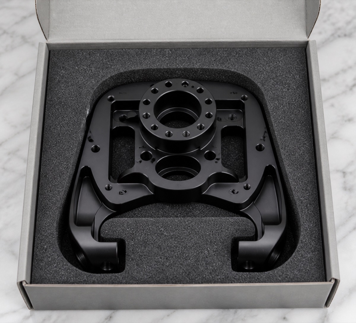
Before anodizing, OEMach confirmed visible faces, hole mouths and cavity corners were clean. After black anodizing, the team rechecked appearance, hole condition, thread feel, key hole clearance and assembly faces before packaging.
Inspection and Lead-Time Control
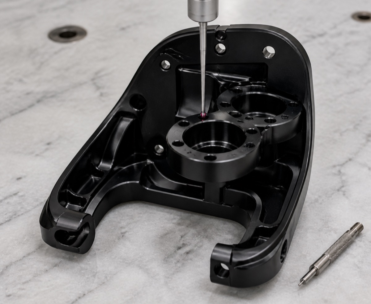
Inspection could not be limited to a dimensional checklist. The center flange hole group was checked relative to the center datum, side holes were checked relative to the assembly direction, and dual-side threads were checked for smooth engagement and consistency on both sides.
For first articles, CMM, dedicated locating gauges or height measurement can confirm hole groups and assembly faces. For small batches, a sampling or full-check plan should be built around key functional dimensions and post-anodizing appearance.
Lead time should include process review, material, roughing, finishing, deburring, cleaning, black anodizing, post-anodizing inspection and protective packaging. For prototype validation, first-article confirmation should be treated as a milestone, not an afterthought.
FAQ
What is the core difficulty in waist linkage assembly machining?
The core difficulty is controlling the datum relationship among the multi-hole center flange, side holes, dual-side threads, cavities and ribs.
Why inspect again after black anodizing?
Black anodizing can reveal scratches, burrs, cleaning residue and hole-mouth issues. Reinspection reduces risk before customer assembly.
How should lead time be planned for complex aluminum structural parts?
CNC machining, deburring, anodizing, post-finish inspection and packaging should all be scheduled, with enough time for first-article confirmation.
Ready to get a quote for your CNC machined parts?
Submit your engineering drawings to qiancj@oemach.com. We support prototype sampling and small-batch production with strict tolerance control.