
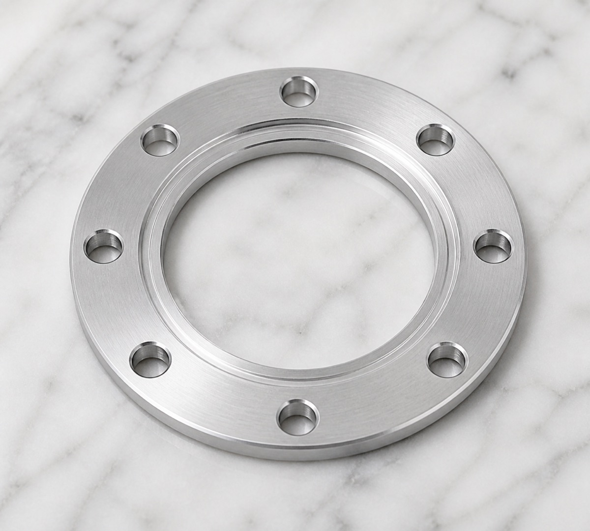
A bearing retaining ring may look like a low-cutting-volume part, but in a humanoid robot joint it can directly affect bearing limitation, fastening stability and assembly feel. The outer diameter is only the visible outline; the inner step, end face and circular hole group are the features that make the part useful in assembly.
This case covers a 6061-T6 aluminum thin ring used around a bearing, rotary node or locating component. OEMach treated the ring as a thin precision component where bore geometry, face contact, hole-group consistency and burr control had to be managed together.
Project Snapshot
| Item | Project detail |
|---|---|
| Part type | Bearing retaining ring / retaining plate for humanoid robot joint assembly |
| Material | 6061-T6 aluminum |
| Structure | Thin circular ring, stepped inner bore, end face, circular small-hole group and small chamfers |
| Surface state | Natural machined aluminum surface |
| Process focus | Thin-ring clamping, stepped bore, end-face stability, hole-group relationship and deburring |
| Inspection focus | Inner bore, step depth, end-face condition, hole diameter, hole pitch, flatness and burrs |
Why the Inner Bore and End Face Matter
In robot joint parts, this type of ring is often installed near bearings, rotating structures or positioning modules. During assembly, the customer will care whether the inner bore slides smoothly, whether the end face seats flat and whether the hole group aligns with the mating part.
If the hole group accumulates positional error, screws can start at an angle. If the stepped inner bore is unstable, neighboring parts may not seat as intended. If a burr remains on the face or hole mouth, a dimension report may still look good while the part feels wrong during assembly.
Machining Challenges
The first challenge is clamping deformation. The part is light and thin, so excessive clamping force can create elastic deformation. After release, the inner bore and end face may no longer stay in the same state as during cutting.
The second challenge is the stepped inner bore. Bore diameter, step depth and end-face perpendicularity need to be controlled as a group. Making the bore size alone is not enough if the shoulder face or end face is unstable.
The third challenge is circular hole-group consistency. Multiple small holes are distributed around the center. If the center datum drifts between operations, each individual hole may measure correctly but the complete assembly pattern can still be difficult to fasten.
OEMach Manufacturing Solution
OEMach first established a stable face and center datum, then planned inner bore, step and hole-group machining around the same reference. During roughing, thin edges were not released too aggressively; during finishing, allowance and clamping pressure were controlled to keep the bore, face and outside profile stable.
For the circular holes, OEMach managed the center datum and hole phase as one coordinate system to reduce accumulated setup error. Chamfers were used for burr removal and assembly friendliness rather than for cosmetic enlargement.
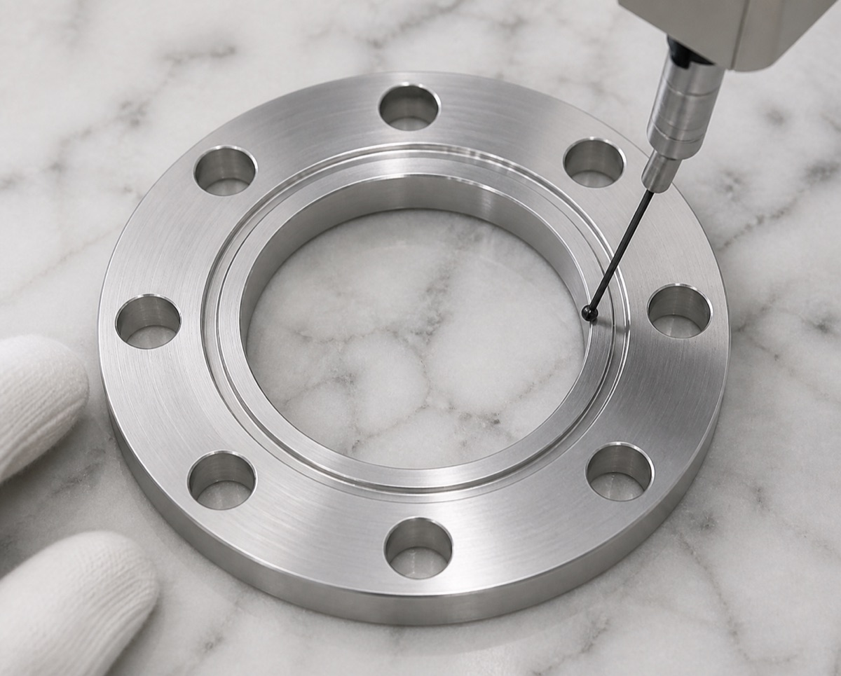
After machining, the part was cleaned to remove coolant, aluminum chips and hole residue. The bore, step, hole mouths, face contact and natural surface were reviewed before packaging.
Inspection and Delivery Control
First-article inspection focused on the center bore, step size, end-face condition, hole diameter, hole spacing and hole-mouth burrs. For thin rings, flatness and the seating feel of the end face should also be included, because a locally lifted edge can affect joint assembly even when basic dimensions pass.
In batch production, it is better to sample the hole group's relationship to the center instead of only checking one hole diameter. For natural machined surfaces, appearance review should include scratches, dents, rolled hole edges and cleanliness.
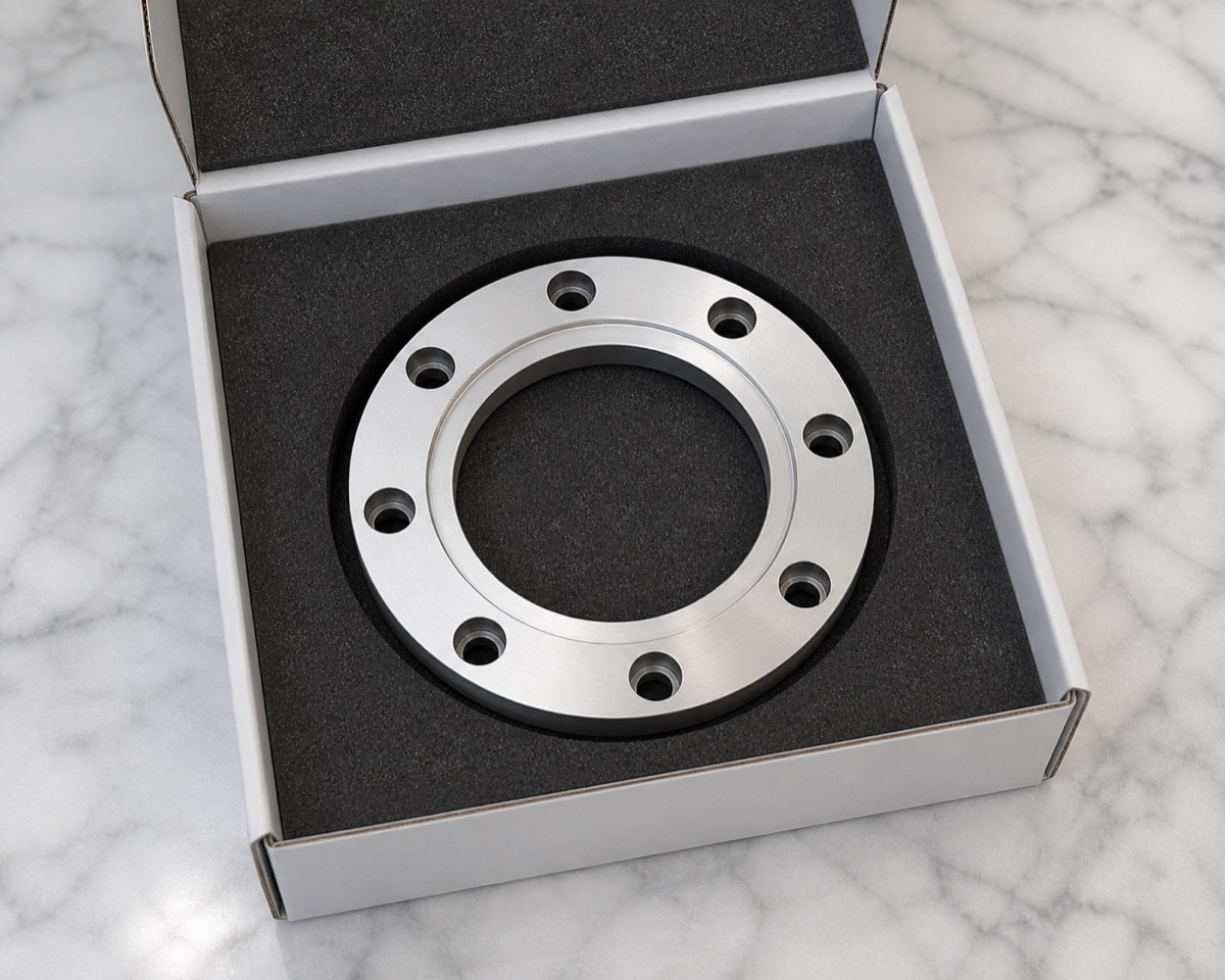
OEMach used form-fit foam, individual separation or compartment packaging so thin end faces and hole mouths would not be damaged during transport. For a retaining ring, delivery quality is not finished until the part reaches the customer's assembly line in a clean and checkable condition.
FAQ
What problems are common in 6061-T6 thin ring machining?
Common issues include clamping deformation, unstable stepped bore geometry, hole-group drift and hole-mouth burrs. They need to be controlled through datum planning, clamping force, tool path and deburring.
Why does a bearing retaining ring need end-face control?
The end face is often a locating or load-contact surface near the bearing. Local warping or burrs can affect seating stability and assembly feel.
How should lead time be estimated for this part?
Material, CNC machining, deburring, cleaning, inspection and protective packaging should all be included. Cutting time alone is not a reliable lead-time estimate.
Ready to get a quote for your CNC machined parts?
Submit your engineering drawings to qiancj@oemach.com. We support prototype sampling and small-batch production with strict tolerance control.