
A waist linkage bracket in a humanoid robot is a load-bearing and positioning component. One end usually connects through a multi-hole flange, the opposite end uses a smaller bore or lug, and the middle bridge transfers load while leaving clearance for neighboring modules.
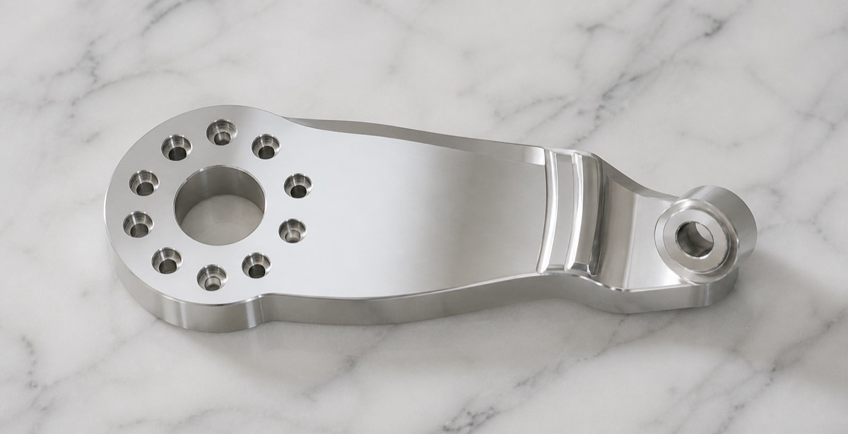
This case study describes a polished waist linkage bracket with a large-end flange, circular hole group, small-end bore, irregular bridge arm and stepped reinforcement areas. The key was not simply to machine every hole, but to keep the spatial relationship among hole groups, contour, height and polished edges stable.
Project Snapshot
| Item | Project detail |
|---|---|
| Part type | Waist linkage bracket / linkage arm component for humanoid robot structure |
| Material | Specified by customer drawing |
| Structure | Multi-hole flange, small-end bore, irregular bridge arm, steps and ribs |
| Finish | Polished appearance with post-finish inspection |
| Process focus | Datum planning, hole-group relationship, small-end bore, bridge-arm deformation and polishing allowance |
| Inspection focus | Big-end center hole, circular small holes, small-end bore, overall length, plane height and burr condition |
Part Function and Engineering Context
In the robot waist, the large flange fixes the component and transfers load, while the small-end bore supports connection or rotation. The bridge arm must maintain stiffness without adding unnecessary weight. If the large-end hole group, small-end bore and bridge profile move relative to each other, assembly alignment and motion clearance can be affected.
For engineering buyers, this type of case matters because it combines several common CNC risks: multi-hole position control, irregular contour machining, local height changes, burr-sensitive bores and polishing after machining.
Machining Challenges
The first challenge is the multi-hole flange. Several holes with different functions sit around the large center hole. Accumulated error, inconsistent chamfers or hole-mouth burrs can affect fastening and locating.
The second challenge is the small-end bore. It sits on a local lug with height difference and limited support. Poor fixturing can shift the bore, change end-face contact or create burrs that affect the mating pin or shaft.
The third challenge is the irregular bridge arm. Width changes, ribs, steps and local thin areas release stress differently during roughing. Later polishing can also soften edges or change visual consistency if the allowance and inspection plan are not clear.
OEMach Manufacturing Solution
OEMach first reviewed three datum relationships: the big-end center datum, the small-end bore datum and the lateral height datum. The process established a stable reference before roughing and kept support in thin or cantilever areas until it was safe to remove.
The big-end center hole and key hole group were controlled early, then the small-end bore and bridge contour were finished under a coordinated datum plan. Irregular profiles and stepped ribs were machined with attention to residual stress, tool-path transitions and edge condition.
Polishing was treated as a process that can influence edges and local appearance, not just as a final shine. OEMach checked burrs, rolled edges, hole mouths and surface scratches before and after polishing.
Inspection, Surface Treatment and Packaging
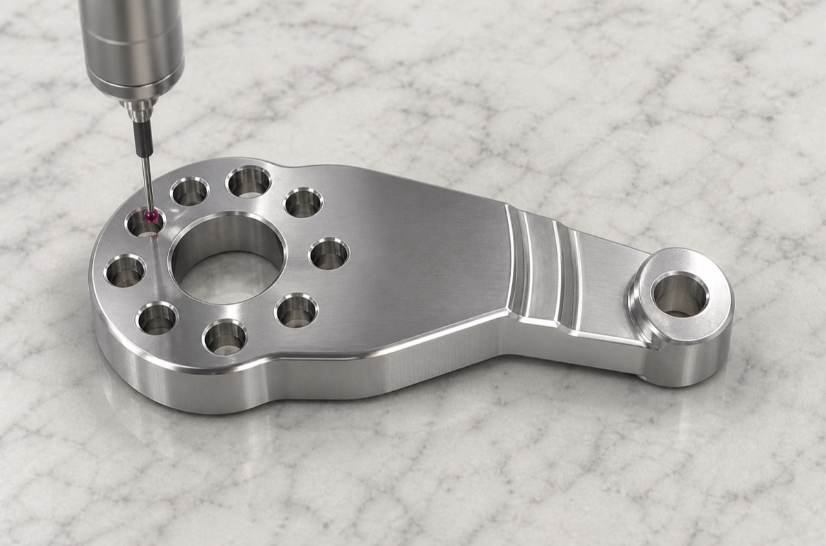
Inspection did not only list single dimensions. The large center hole, circular small holes, small-end bore and overall length were checked as assembly-related groups. When needed, CMM, dedicated gauges or height measurement can confirm hole group positions, plane height and the relationship between key holes.
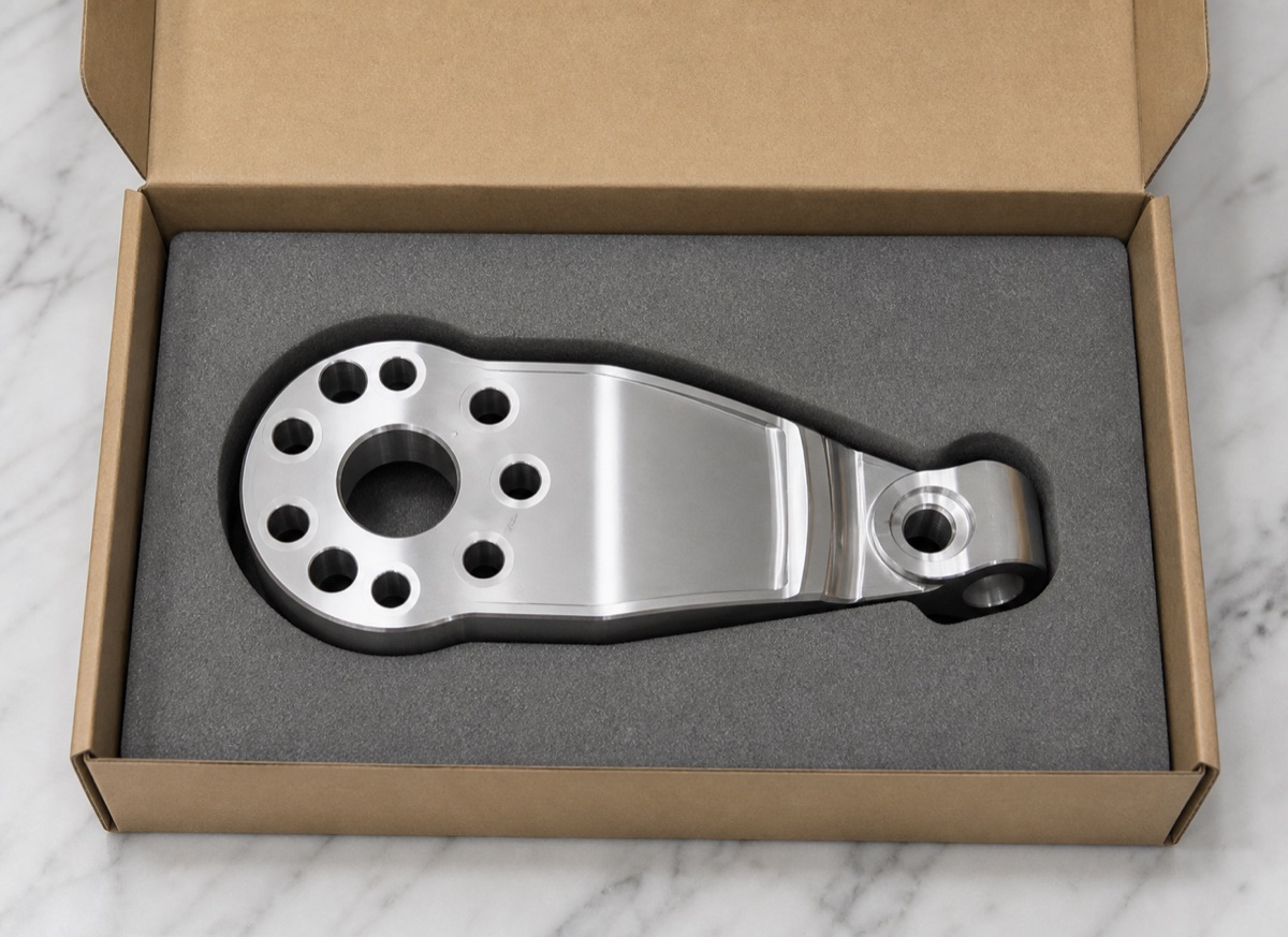
After polishing, OEMach rechecked hole-mouth edges, chamfer consistency, polishing direction, scratches and visible surface condition. The part was then packed with form-fit foam so polished faces, bore mouths and irregular contours would not be damaged in transport.
Result for Prototype and Small-Batch Delivery
This case shows that complex linkage brackets test a supplier's closed-loop capability. Understanding function, datum planning, fixturing, rough/finish separation, polishing, final inspection and packaging is more important than only reporting that the holes can be machined.
FAQ
What is difficult about machining a humanoid robot waist linkage bracket?
The main difficulty is controlling the spatial relationship among the multi-hole flange, small-end bore, irregular bridge arm and local height differences.
Why inspect again after polishing?
Polishing can affect hole mouths, edges and local appearance. Post-polish inspection helps prevent dimensional or assembly-boundary changes after surface finishing.
How should lead time be planned for complex irregular brackets?
The schedule should include process review, first-article confirmation, polishing, final inspection and packaging so batch rework is reduced.
Ready to get a quote for your CNC machined parts?
Submit your engineering drawings to qiancj@oemach.com. We support prototype sampling and small-batch production with strict tolerance control.