
The ankle joint of a humanoid robot has limited space and carries repeated motion. A small connecting shaft may look simple, but it can define fit, locking relationship, stop position or sensor alignment. If the outside diameter is too large, assembly resistance increases. If it is too small, clearance and motion noise can increase.
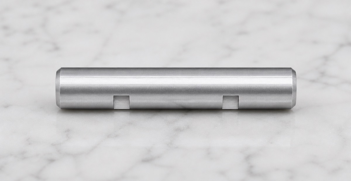
This case study covers a 6061-T6 aluminum ankle connecting shaft with two rectangular milled slots and chamfered ends. OEMach focused on the shaft axis as the main datum, then controlled outside diameter, slot phase, slot burrs and clean packaging as one process.
Project Snapshot
| Item | Project detail |
|---|---|
| Part type | Ankle connecting shaft for humanoid robot joint assembly |
| Material | 6061-T6 aluminum |
| Structure | Small-diameter shaft, end chamfers and two rectangular milled slots |
| Process route | CNC turning for OD and ends, followed by controlled slot milling |
| Process focus | OD stability, end-face perpendicularity, slot width/depth and slot phase |
| Inspection focus | Outside diameter, roundness, slot relationship, chamfer quality and slot-edge burrs |
Part Function and Engineering Context
A robot ankle shaft often connects compact brackets, bearings, limit structures or sensor-related parts. The shaft does not work only by its diameter; the slots may define locking, orientation, cable clearance, limiter engagement or fixture relation in the customer's assembly.
For this reason, slot phase and slot edge quality are important. A shaft can pass OD inspection but still fail assembly if the two milled slots are not in the expected angular relationship or if slot burrs scratch the mating part.
Machining Challenges
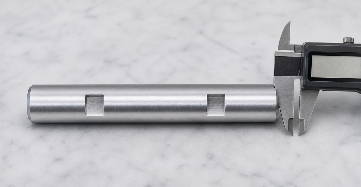
The first challenge is maintaining the outside diameter and roundness after turning and slot milling. A small shaft can be marked by hard clamping or affected by repeated setup transfer.
The second challenge is slot phase. The two rectangular slots must remain consistent relative to the shaft axis and end reference. If the part is simply turned first and then clamped casually for milling, angular error can appear.
The third challenge is burr control around slots and end chamfers. Slot edges are contact areas during assembly. Burrs or rolled edges can change the fit feel, interfere with mating parts or create visible quality concerns.
OEMach Manufacturing Solution
OEMach treated the shaft axis as the primary datum. OD, end face and slot machining were planned around that axis to reduce error from secondary setup. Depending on batch and tolerance needs, soft jaws, V-block support or a dedicated fixture can be used for slot milling after turning.
The process started with turning the OD, end face and chamfer features. Slot milling was then controlled for width, depth, bottom flatness, distance from end reference and angular relationship. Tool wear and chip evacuation were monitored because both affect slot edge quality.
Deburring was not left as a general final wipe. Slot edges, end chamfers and OD transition areas were checked independently so burr removal would not create flats, scratches or over-rounded slot corners.
Inspection, Surface Treatment and Packaging
Inspection avoided measuring the OD only near chamfered areas. OEMach checked OD stability, roundness, turning marks, end-face condition, slot width, slot depth, slot relationship and burrs. When phase is critical, a fixture or CMM can verify the angular relationship between slots.
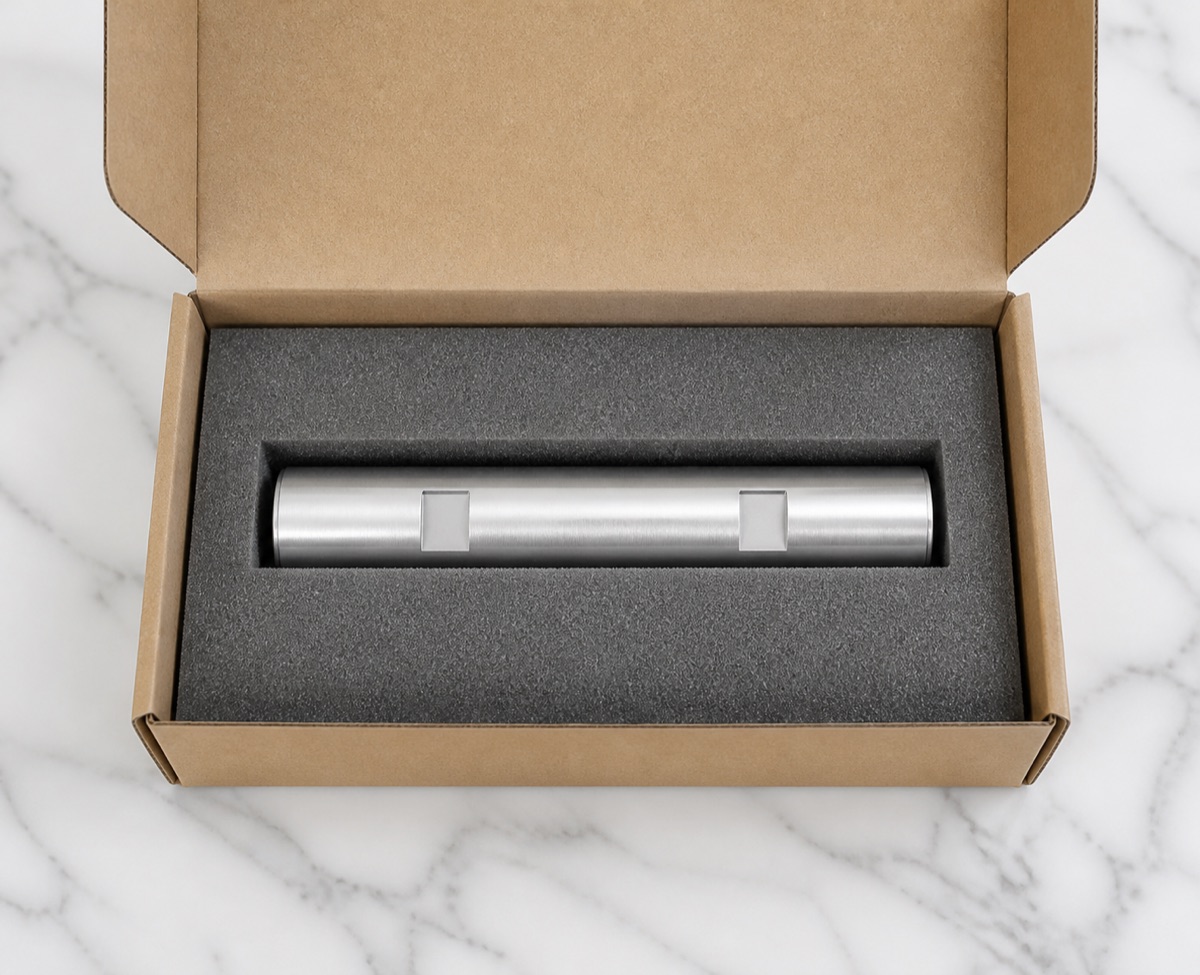
Small shafts should not roll freely in packaging. OEMach used foam grooves or separated positioning to prevent rolling, mixed contact, end-face dents and surface scratches before the parts reach the customer's assembly line.
Result for Prototype and Small-Batch Delivery
This shaft case shows why small turned-and-milled robot parts need process discipline. The lead time should include material, fixture preparation, first-article confirmation, turning, slot milling, deburring, cleaning, inspection and packaging. Compressing only the machining time does not protect assembly quality.
FAQ
Why does slot phase matter on a robot ankle connecting shaft?
The slots may control locking, orientation, stop position or mating clearance. If phase shifts, the shaft can pass diameter inspection but fail in the assembly relationship.
What should be checked besides outside diameter?
Roundness, end-face condition, chamfers, slot width, slot depth, slot phase, burrs and surface marks should also be checked.
How should small shafts be packed for delivery?
They should be separated or held in foam grooves so they cannot roll, collide or damage end faces and slot edges during transport.
Ready to get a quote for your CNC machined parts?
Submit your engineering drawings to qiancj@oemach.com. We support prototype sampling and small-batch production with strict tolerance control.