
In a humanoid robot joint, a zero-position or limit stop block is a small part with a large functional impact. It helps define the mechanical stop, supports assembly positioning and keeps the joint relationship repeatable. If the holes, arc boundary or local flatness drift, the part may still look acceptable but the joint can feel tight, misaligned or inconsistent during assembly.
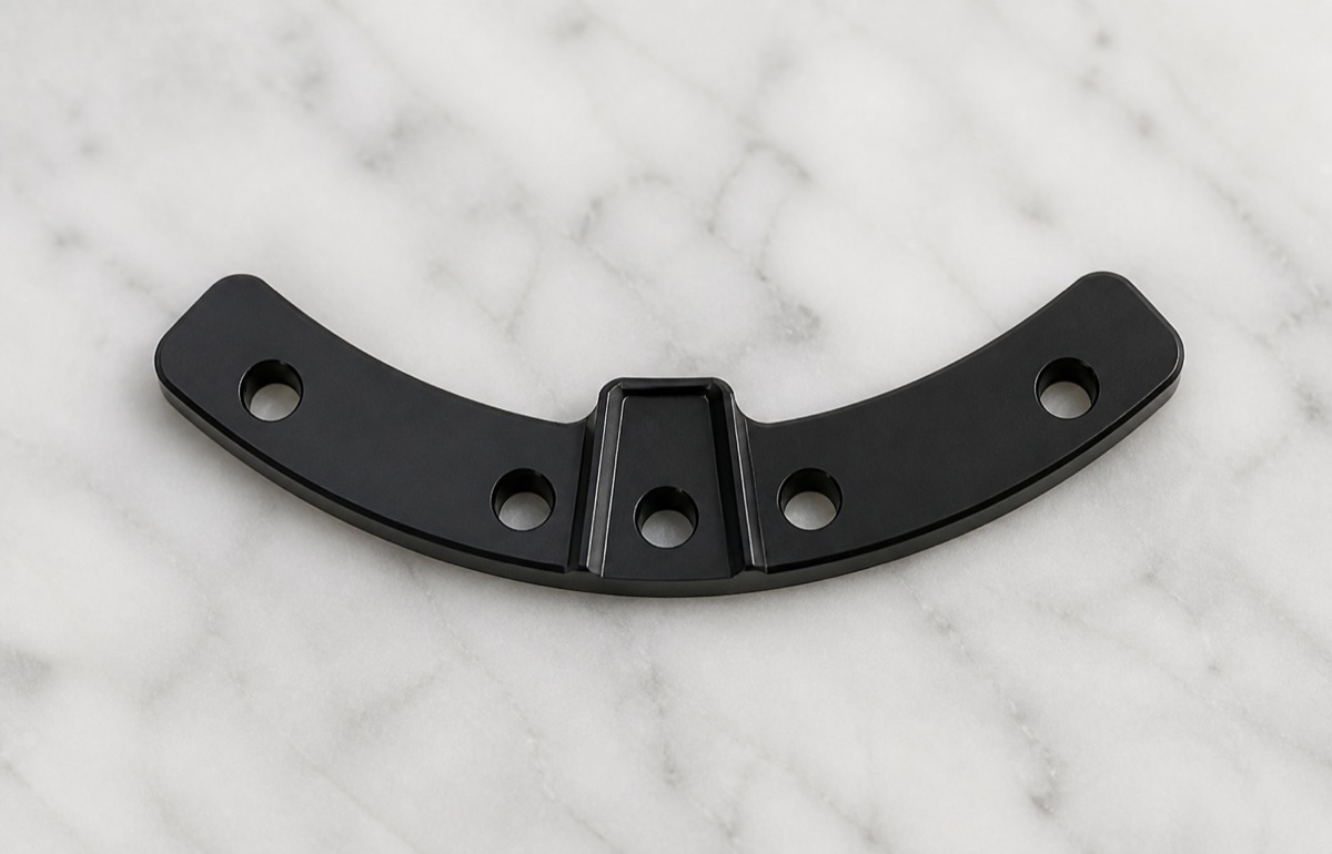
This case study covers a 6061-T6 aluminum curved stop block with a black finished surface. The part is thin, curved and interrupted by multiple small holes, with a raised center area and narrow edge transitions. OEMach treated the job as a relationship-control part rather than a simple profile plate.
Project Snapshot
| Item | Project detail |
|---|---|
| Part type | Curved zero-position / limit stop block for humanoid robot joints |
| Material | 6061-T6 aluminum |
| Structure | Thin curved plate, central raised area, small hole groups and arc edges |
| Finish | Black anodized finish |
| Process focus | Arc profile, hole-to-arc relationship, thin-part clamping and burr control |
| Inspection focus | Hole diameter, hole pitch, arc contour, flatness, edge condition and finish appearance |
Part Function and Engineering Context
For robot joints, the stop block usually works together with a mating bracket, sensor datum or mechanical limiter. The customer cares less about one isolated dimension and more about whether the whole part keeps the intended relationship among the arc, holes and contact areas.
Because this part is small and thin, small burrs and local deformation become visible during assembly. A raised burr at a hole mouth can lift the part from its mating face. Excessive deburring around the arc can change the boundary. A non-uniform black finish can also make dents, scratches and edge defects easier to see.
Machining Challenges
The first challenge is the arc profile. The outer and inner curved edges must relate correctly to the hole pattern and central feature. If the arc is machined without a stable datum strategy, the hole-to-edge relationship can drift even when each single feature is within size.
The second challenge is thin-part clamping. 6061-T6 aluminum is machinable, but a thin curved part can spring back after unclamping. Excessive clamping pressure, uneven support or aggressive finishing can affect flatness and edge consistency.
The third challenge is finish preparation. Black anodized surfaces make hole burrs, scratches, cutter marks and dents more visible. Edges must be deburred enough for assembly, but not rounded so much that the arc boundary or hole chamfer loses control.
OEMach Manufacturing Solution
OEMach reviewed the arc, center raised area and small holes as one datum relationship before machining. The process kept support tabs or fixture support where useful, then machined key holes and the center feature before finishing the inner and outer arcs.
For thin sections, cutting force and clamping pressure were kept conservative. Tool paths were arranged to reduce local vibration and avoid overcutting at narrow transitions. Deburring was handled as a controlled step covering hole mouths, end faces, arc edges and small transitions.
Before surface treatment, the part was cleaned and inspected for burrs, scratches, dents and inconsistent chamfers. After black finishing, OEMach rechecked appearance, hole condition and the key assembly surfaces so that finish quality did not hide a dimensional issue.
Inspection, Surface Treatment and Packaging
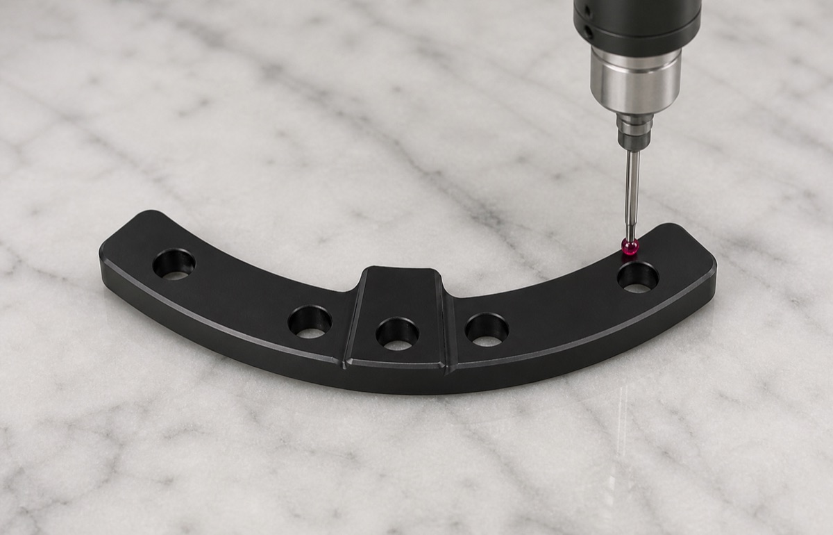
Inspection covered hole diameter, hole pitch, arc profile, local thickness, flatness, burr condition and black surface appearance. For first articles or critical parts, projection measurement, CMM, height measurement or dedicated fixtures can be used to confirm the relationship between arc and holes.
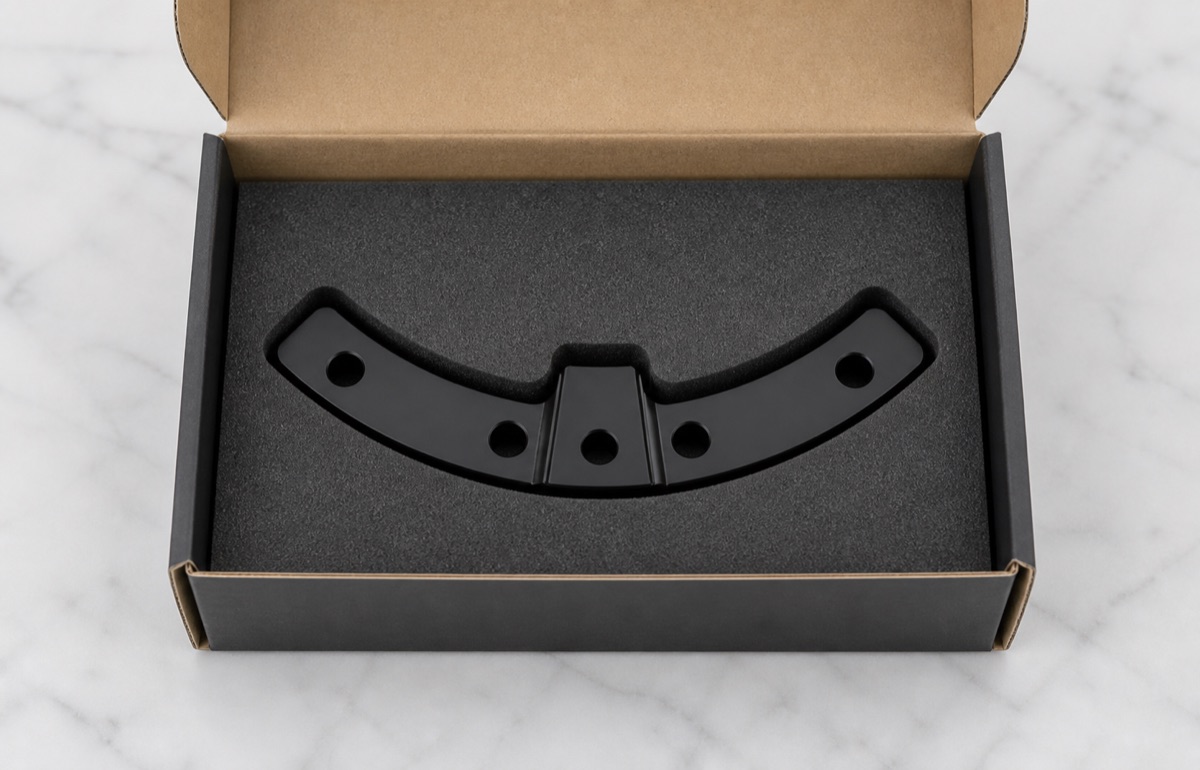
Packaging was treated as part of quality control. Black finished parts should not be loose in a bag or stacked directly. OEMach used foam positioning and individual separation to reduce rubbing, bright impact spots and damage around the curved edges.
Result for Prototype and Small-Batch Delivery
This project shows that small robot stop blocks need the same closed-loop control as larger structural parts. DFM review, fixture support, staged machining, deburring, pre-finish inspection, post-finish recheck and protected packaging all help the part arrive ready for assembly.
FAQ
Why are curved zero-position stop blocks difficult to machine?
The difficulty is not only the part size. The arc profile, small holes, thin wall, local flatness, burrs and black finish all affect how the block fits and stops the joint.
Why inspect burrs before black anodizing?
Black finishing makes burrs, scratches and uneven chamfers easier to see. Burrs left at hole mouths can also affect how the stop block seats during assembly.
Can this type of robot stop block be made quickly for prototypes?
Yes, but the schedule should include machining, deburring, surface treatment, post-finish inspection and protected packaging rather than only CNC cutting time.
Ready to get a quote for your CNC machined parts?
Submit your engineering drawings to qiancj@oemach.com. We support prototype sampling and small-batch production with strict tolerance control.